Construction
- 2x or 3x Ikea LACK table
- 4x Neodymium magnets 20mm x 6mm x 2mm
- 3x Plexi 440 x 440 mm, 3mm thick (if you’re in the US, try Queen City Polymers)
- 2x Plexi 220 x 440 mm, 3mm thick
Electronics
- Fire/smoke detector
- Indoor/Outdoor Thermometer
- LED stripe 24V, 30 cm
- 24V for MK3, 12V for MK2/S
- If you want to use a 12V LED strip with the MK3, use a separate power supply.
- Twin cable, 100 cm
- 2x WAGO 221 or similar compact lever connector
Screws
- 12x 6×20 mm (12 x 3/4″)
- 4x 6×50 mm (12 x 2″)
Printed parts
- Upper table (enclosure box)
- Lower table (support table)
- Spool holders
Tools
- Philips screwdriver
- Allen keys
- Super Glue
- Drill + 3 mm wood drill + 10 mm wood drill
- Measuring tape
- Marker
Enclosure (upper table) assembly
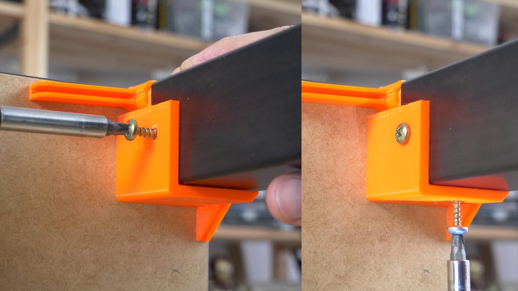
Upper corner standoffs installation
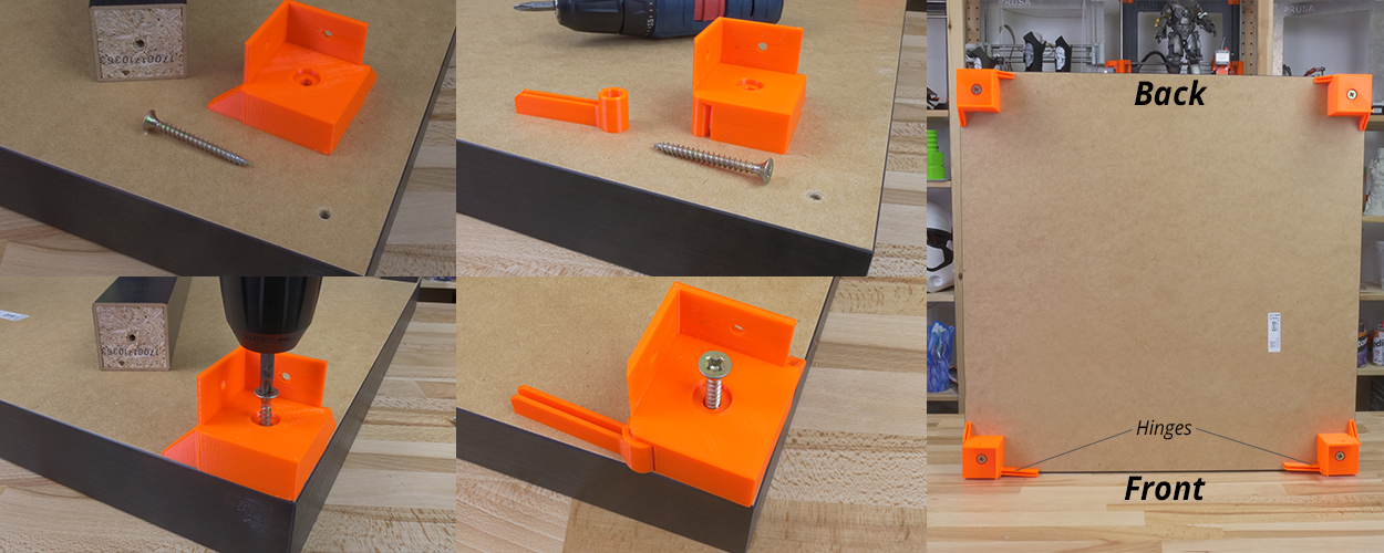
Attaching the legs
LED stripe
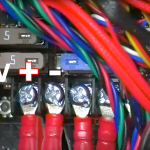
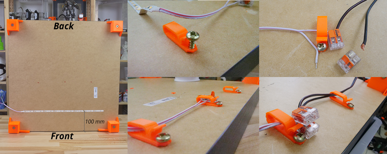
For about $12, you can buy an LED strip with a power supply, like this one. However, if you’re feeling a bit adventurous and have some experience with wiring up electronics, you can power the LEDs directly from the printers power supply. Remember, that the MK3 runs on 24V, whereas MK2/S runs on 12V, so make sure you buy the correct LEDs.
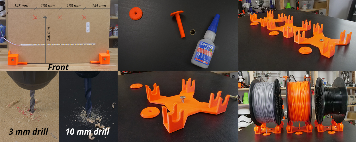
Spool holders
Smoke detector installation
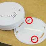
Place the smoke detector in the rear part of the table so it will not obstruct filament insertion or won’t get in the way when you’re taking the printer out from the box.
Bottom corner standoffs installation
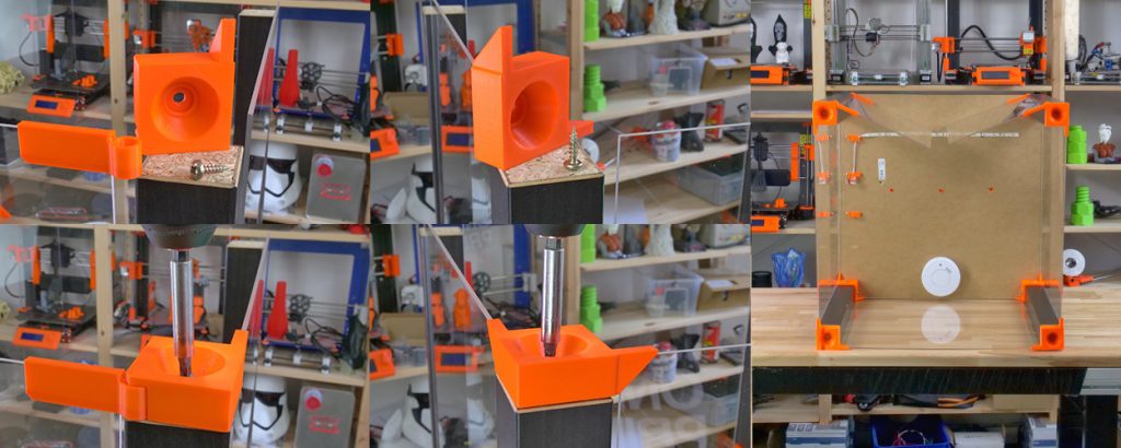
Before you start screwing the bottom standoffs, make sure you place the Plexiglass in first. As soon as you tighten the standoffs, the Plexiglass will be fixed in place, and you won’t be able to remove it. This means you can easily lift this section of the enclosure without worrying that the glass would fall out. Note, that one of the four standoffs has a hole for cable pass-through. Make sure you place this standoff on the left side so that the cables can be routed directly to the EINSY board.
Support table (lower table) assembly
PSU holder
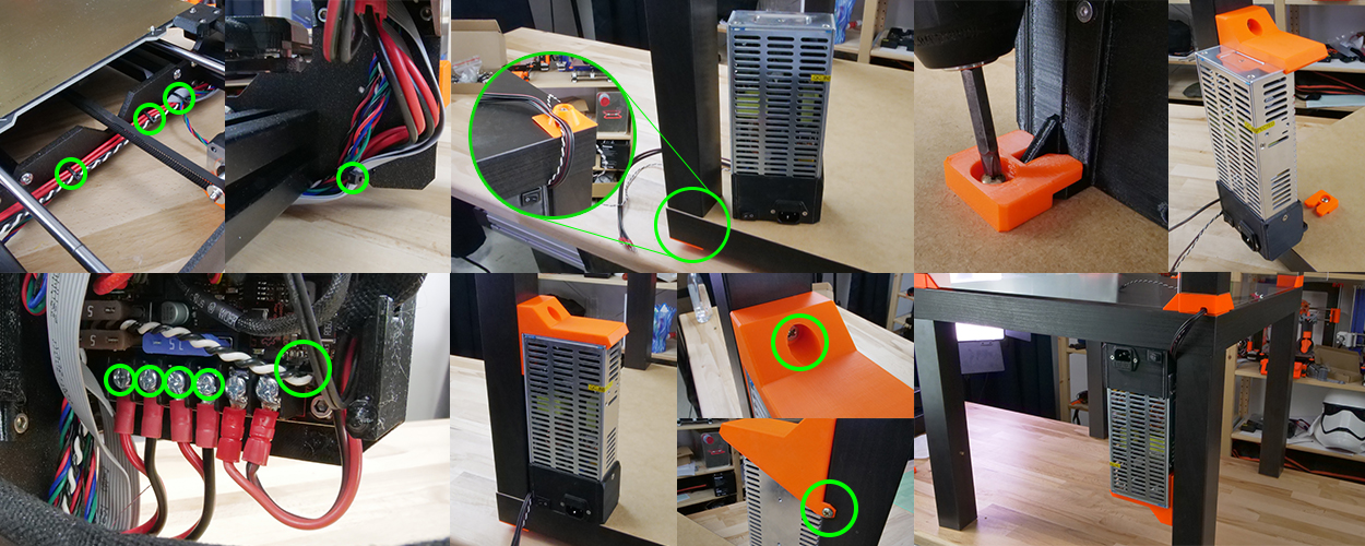
Electronics do not thrive in higher temperatures inside the enclosure. To preserve PSU in good condition, it’s better to place it out of the box. It is even safer!
- Unplug the printer from the power socket. Remove zip ties on the frame to release PSU cables. (Tighten the rest of the cables with new zip ties.)
- Disconnect the cables from the EINSY board. Do not forget to unplug the Power panic sensor as well.
- Unscrew the PSU form the frame.
- Hold the PSU next to the rear left leg (the one with the cable pass-through). Tighten the PSU holder printed part with two screws and then install PSU catcher printed part.
- PSU is now fixed, but it is possible to slide it out when you need it.
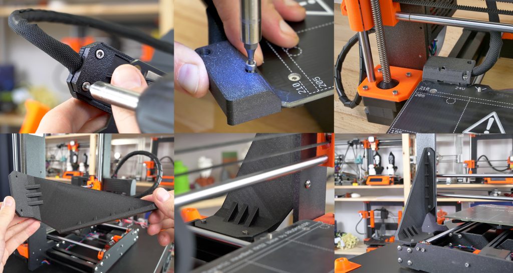
- You can replace the PSU on the frame with this printed part to ensure the rigidity of the frame.
Frame brace and right-angle cable cover
After removing the power supply from the frame, it’s possible to replace it with a printed part and ensure frame stiffness. The heatbed cables may hit the plexiglass in the back of the enclosure. To prevent this from happening, print an alternative 60 degree heatbed cable cover. (EDIT: Users reported several problems with the right angle one shown in the video and on the pictures below, so we switched the suggestion to the 60 degree one).
Plugs fixing and magnetic handles
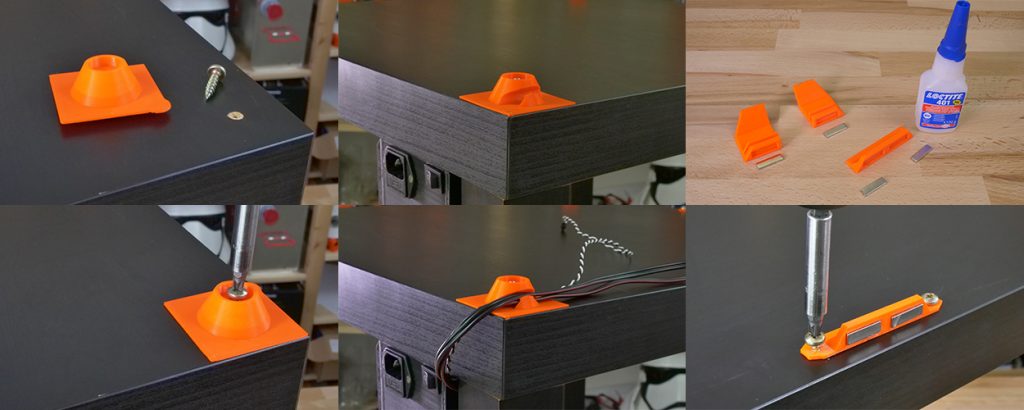
Fix the four bottom plugs. One of them has a hole for cable pass-through. Place it in the rear left corner of the enclosure. Glue two magnets to the door stopper and screw it to the front of the table. Leave enough space for the plexiglass and the handles (1 cm).
Finished enclosure
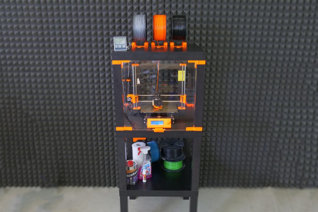
Now just stack the two tables on top of each other and the enclosure is complete. Optionally, you can add another Ikea Lack table to the bottom to raise the printer to a more comfortable height.
Material source
https://www.printables.com/model/17-original-prusa-i3-mk3-enclosure-ikea-lack-table-pr/files
https://www.printables.com/model/13490-prusa-i3-mk3s-black-psu
