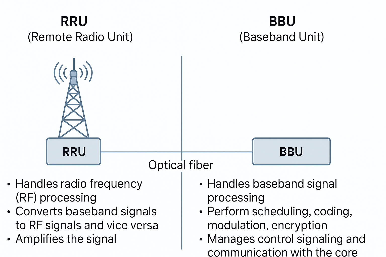
The ePDG has the following key features:
- Support for the IPSec/IKEv2-based SWu interface between the ePDG and the WLAN (Wireless LAN) UEs.
- Routing of packets between the WLAN UEs and the Cisco P-GW (Packet Data Network Gateway) over the S2b interface via GTPv2 or PMIPv6 (Proxy Mobile IP version 6) protocol.
- P-GW selection via DNS client functionality to provide PDN (Packet Data Network) connectivity to the WLAN UEs.
- Support for passing assigned IPv4/IPv6 address configurations from the P-GW to the WLAN UEs.
- Support for the Diameter-based SWm interface between the ePDG and the external 3GPP AAA server.
- Tunnel authentication and authorization for IPSec/PMIPv6/GTPv2 tunnels using the EAP-AKA (Extensible Authentication Protocol – Authentication and Key Agreement) authentication method between the 3GPP AAA server and the WLAN UEs.
- Encapsulation and decapsulation of packets sent over the IPSec/PMIPv6/GTPv2 tunnels.
- Hosts a MAG (Mobile Access Gateway) function, which acts as a proxy mobility agent in the E-UTRAN/EPC network and uses PMIPv6 signaling to provide network-based mobility management on behalf of the WLAN UEs attached to the network.
Platform Requirements
The ePDG service runs on a Cisco ASR 5000/ASR 5500 (DPC1/DPC2) chassis running the StarOS operating system and Virtualized Packet Core (VPC) platforms. The chassis can be configured with a variety of components to meet specific network deployment requirements. For additional information, see the installation guide for the chassis and/or contact your Cisco account representative.
| Note | If the ePDG is being deployed in Cisco Virtual Packet Core (VPC) on a Cisco UCS server, as of VPC release 3.5 the software automatically detects the presence of the Intel Mezz Crypto Card. If you configure the virtual machine of the VPC to pass through this chipset, the VPC automatically utilizes the Intel Mezz Crypto Card for encryption and decryption of packets. |
Licenses
The ePDG is a licensed Cisco product. Separate session and feature licenses may be required. Contact your Cisco account representative for detailed information on specific licensing requirements. For information on installing and verifying licenses, see „Managing License Keys“ in the System Administration Guide.
Network Deployment(s) and Interfaces
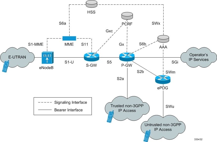
This section describes the ePDG as it provides secure access from the WLAN UEs to the Cisco P-GW and a connection to the PDN (Packet Data Network) in the E-UTRAN/EPC (Evolved UTRAN/Evolved Packet Core) network.
The figure below shows the ePDG terminating the SWu interface from the untrusted non-3GPP IP access network and providing secure access to the Cisco P-GW and a connection to the PDN via the PMIPv6/GTPv2 S2b interface. It also shows the network interfaces used by the Cisco MME, S-GW, and P-GW in the E-UTRAN/EPC network.Figure 1. The ePDG in the E-UTRAN/EPC Network
Network Elements
This section provides a description of the network elements that work with the ePDG in the E-UTRAN/EPC network. For untrusted non-3GPP IP access, note that the network architecture assumes the access network elements do not perform any function other than delivering packets.
ePDG
The ePDG is responsible for interworking between the EPC and untrusted non-3GPP networks that require secure access, such as a WiFi, LTE metro, and femtocell access networks.
eNodeB
The eNodeB (evolved Node B) is the termination point for all radio-related protocols. As a network, E-UTRAN is simply a mesh of eNodeBs connected to neighboring eNodeBs via the X2 interface.
MME
The Cisco MME (Mobility Management Entity) is the key control node for the LTE access network. It works in conjunction with the eNodeB and the Cisco S-GW to control bearer activation and deactivation. The MME is typically responsible for selecting the Cisco P-GW for the UEs to access the PDN, but for secure access from untrusted non-3GPP IP access networks, the ePDG is responsible for selecting the P-GW.
S-GW
The Cisco S-GW (Serving Gateway) routes and forwards data packets from the 3GPP UEs and acts as the mobility anchor during inter-eNodeB handovers. The S-GW receives signals from the MME that control the data traffic. Every 3GPP UE accessing the EPC is associated with a single S-GW.
P-GW
The Cisco P-GW (Packet Data Network Gateway) is the network node that terminates the SGi interface towards the PDN. The P-GW provides connectivity to external PDNs for the subscriber UEs by being the point of entry and exit for all subscriber UE traffic. A subscriber UE may have simultaneous connectivity with more than one P-GW for accessing multiple PDNs. The P-GW performs policy enforcement, packet filtering, charging support, lawful interception, and packet screening. The P-GW is the mobility anchor for both trusted and untrusted non-3GPP IP access networks. For PMIP-based S2a and S2b interfaces, the P-GW hosts the LMA (Local Mobility Anchor) function.
3GPP AAA Server
The 3GPP AAA (Authentication, Authorization, and Accounting) server provides UE authentication via the EAP-AKA (Extensible Authentication Protocol – Authentication and Key Agreement) authentication method.
HSS
The HSS (Home Subscriber Server), is the master user database that supports the IMS (IP Multimedia Subsystem) network entities. It contains subscriber profiles, performs subscriber authentication and authorization, and provides information about the subscriber’s location and IP information.
PCRF
The PCRF (Policy and Charging Rules Function) determines policy rules in the IMS network. The PCRF operates in the network core, accesses subscriber databases and charging systems, and makes intelligent policy decisions for subscribers.
Logical Network Interfaces
| Interface | Description |
|---|---|
| SWu Interface | The secure interface to the WLAN UEs in the untrusted non-3GPP IP access network, the SWu interface carries IPSec tunnels. The ePDG uses IKEv2 signaling to establish IPSec tunnels between the UEs and the ePDG. It also supports the negotiation of configuration attributes such as IP address, DNS, and P-CSCF in the CP (Configuration Parameters) payload of IKE_AUTH Request and Response messages. |
| SWm Diameter Interface | The interface to the 3GPP Diameter AAA server, the SWm interface is used for WLAN UE authentication. It supports the transport of mobility parameters, tunnel authentication, and authorization data. The EAP-AKA (Extensible Authentication Protocol – Authentication and Key Agreement) method is used for authenticating the WLAN UEs over this interface. SWm interface supports both TCP and SCTP protocols. |
| S2b Interface | The interface to the P-GW, the S2b interface runs PMIPv6 (Proxy Mobile IP version 6)/GTPv2 protocol to establish WLAN UE sessions with the P-GW. It also supports the transport of P-CSCF attributes and DNS attributes in PBU (Proxy-MIP Binding Update)/Create Session Request and PBA (Proxy-MIP Binding Acknowledgement)/Create Session Response messages as part of the P-CSCF discovery performed by the WLAN UEs. |
Transport Combinations
| IP Address Allocated by the P-GW for the WLAN UEs | IPSec Tunnels (between the WLAN UEs and the ePDG) | GTPv2 | Combination Supported for Deployment? |
|---|---|---|---|
| IPv4 | IPv4 | IPv4 | Yes |
| IPv4 | IPv6 | IPv6 | Yes |
| IPv4 | IPv6 | IPv4 | Yes |
| IPv4 | IPv4 | IPv6 | Yes |
| IPv6 | IPv4 | IPv4 | Yes |
| IPv6 | IPv6 | IPv6 | Yes |
| IPv6 | IPv6 | IPv4 | Yes |
| IPv6 | IPv4 | IPv6 | Yes |
| IPv4v6 | IPv4 | IPv4 | Yes |
| IPv4v6 | IPv6 | IPv6 | Yes |
| IPv4v6 | IPv4 | IPv6 | Yes |
| IPv4v6 | IPv6 | IPv4 | Yes |
The table below lists the IPv4/IPv6 transport combinations for the ePDG and whether each combination is supported for deployment in this release.
PMIPv6 S2b IPv6 transport is qualified.
Features and Functionality
This section describes the ePDG features and functions, as follows:
- ePDG Service
- IKEv2 and IPSec Encryption
- Dead Peer Detection
- Child SA Rekeying
- Support for MAC Address of WiFi Access Points
- AAA Server Groups
- EAP Authentication
- IPv6 Capabilities
- Static Selection
- Dual Stack Support
- Inter-access Handover Support
- Mobile Access Gateway Function
- IPv6 Router Advertisement Support
- DNS Request Support
- P-CSCF Request Support
- Multiple PDN Support
- Default APN Support
- Congestion Control
- Session Recovery Support
- DSCP and 802.1P Marking
- ePDG P-GW selection
- IPSec Cookie Threshold
- Threshold Crossing Alerts
- Bulk Statistics Support
- ICSR Support
- IKEv2 RFC 5996 Support
- IPv6 Support on IPSec SWU Interface
- Narrowing Traffic Selectors
- Static IP Address Allocation Support
- ePDG and PGW Support on the Same Chassis (with GTPv2)
- ICSR-VoLTE Support
- Local PGW Resolution Support
- Non UICC Device Support Using Certificate Based Authentication
- EAP-MSCHAPv2/EAP-TLS/EAP-TTLS Based Support For NON UICC Devices
- Emergency APN Support on ePDG
- Passing on UE Tunnel Endpoint Address over SWm Support
- Custom SWm to SWu error code mapping
- ePDG Bearer Duration KPIs
- Data Buffering Support for DL Packets Before Session Establishment
- Downlink DSCP Marking(SWu)
- ePDG Fast Re-Auth Support
- ePDG Offline charging
- UE Local IP Address IE in the S2B Interface over GTPv2
- ePDG Service
- IKEv2 and IPSec Encryption
- Dead Peer Detection
- Child SA Rekeying
- Support for MAC Address of WiFi Access Points
- AAA Server Groups
- EAP Authentication
- IPv6 Capabilities
- General Call Flow
- Static and Dynamic P-GW Selection
- Dual Stack Support
- Inter-access Handover Support
- Mobile Access Gateway Function
- IPv6 Router Advertisement Support
- DNS Request Support
- P-CSCF Request Support
- Multiple PDN Support
- Default APN Support
- Congestion Control
- Session Recovery Support
- ICSR Support
- ePDG P-GW selection
- S2b GTPv2 support
- DSCP and 802.1P Marking
- IPSec Cookie Threshold
- Threshold Crossing Alerts
- Bulk Statistics Support
- IKEv2 RFC 5996 Support
- IPv6 Support on IPSec SWU Interface
- Narrowing Traffic Selectors
- Static IP Address Allocation Support
- ePDG and PGW Support on the Same Chassis (with GTPv2)
- ICSR-VoLTE Support
- Local PGW Resolution Support
- Non UICC Device Support Using Certificate Based Authentication
- EAP-MSCHAPv2/EAP-TLS/EAP-TTLS Based Support For NON UICC Devices
- Emergency APN Support on ePDG
- Passing on UE Tunnel Endpoint Address over SWm Support
- Passing on IMEI to AAA for EIR Support on WiFi
- Custom SWm to SWu error code mapping
- ePDG Bearer Duration KPIs
- Data Buffering Support for DL Packets Before Session Establishment
- Downlink DSCP Marking(SWu)
- ePDG Fast Re-Auth Support
- ePDG Offline charging
- UE Local IP Address IE in the S2B Interface over GTPv2
- Lawful Intercept
- IKEv2 Fragmentation Support
ePDG Service
The ePDG service enables the WLAN UEs in the untrusted non-3GPP IP access network to connect to the E-UTRAN/EPC network via a secure IPSec interface.During configuration, you create the ePDG service in an ePDG context, which is a routing domain in the system. Context and service configuration for the ePDG includes the following main steps:
- Configure the IPv4/IPv6 address for the service: This is the IP address of the ePDG to which the WLAN UEs attempt to connect, sending IKEv2 messages to this address to establish IPSec tunnels.
- Configure the name of the crypto template for IKEv2/IPSec: A crypto template is used to define an IKEv2/IPSec policy. It includes IKEv2 and IPSec parameters for keepalive, lifetime, NAT-T, and cryptographic and authentication algorithms. There must be one crypto template per ePDG service.
- The name of the EAP profile: The EAP profile defines the EAP authentication method and associated parameters.
- IKEv2 and IPSec transform sets: Transform sets define the negotiable algorithms for IKE SAs (Security Associations) and Child SAs to enable calls to connect to the ePDG.
- The setup timeout value: This parameter specifies the session setup timeout timer value. The ePDG terminates a UE connection attempt if the UE does not establish a successful connection within the specified timeout period. The default value is 60 seconds.
- Max-sessions: This parameter sets the maximum number of subscriber sessions allowed by the ePDG service. The default value is 1,000,000 and is subject to license limitations.
- DNS client: DNS client configuration is needed for P-GW selection.
IKEv2 and IPSec Encryption
The ePDG supports IKEv2 (Internet Key Exchange version 2) and IPSec (IP Security) ESP (Encapsulating Security Payload) encryption as per RFCs 4303 and 5996. IKEv2 and IPSec encryption enables network domain security for all IP packet-switched networks in order to provide confidentiality, integrity, authentication, and anti-replay protection. These capabilities are ensured through use of cryptographic techniques.
The data path from the ePDG supports mixed inner IPv4 and IPv6 addresses in the same Child SA for ESP (Encapsulating Security Payload) encapsulation and decapsulation when the Any option is configured in the payload, regardless of the IP version of the outer protocol.
Supported Algorithms
| Protocol | Type | Supported Options |
|---|---|---|
| Internet Key Exchange version 2 | IKEv2 Encryption | DES-CBC, 3DES-CBC, AES-CBC-128, AES-CBC-256, AES-128-GCM-128, AES-128-GCM-64, AES-128-GCM-96, AES-256-GCM-128, AES-256-GCM-64, AES-256-GCM-96Note AES-GCM algorithms are supported only on VPC-DI and VPC-SI Platform. |
| IKEv2 Pseudo Random Function | PRF-HMAC-SHA1, PRF-HMAC-MD5, AES-XCBC-PRF-128 | |
| IKEv2 Integrity | HMAC-SHA1-96, HMAC-SHA2-256-128, HMAC-SHA2-384-192. HMAC-SHA2-512-256, HMAC-MD5-96, AES-XCBC-96 | |
| IKEv2 Diffie-Hellman Group | Group 1 (768-bit), Group 2 (1024-bit), Group 5 (1536-bit), Group 14 (2048-bit) | |
| IP Security | IPSec Encapsulating Security Payload Encryption | NULL, DES-CBC, 3DES-CBC, AES-CBC-128, AES-CBC-256 |
| Extended Sequence Number | Value of 0 or off is supported (ESN itself is not supported) | |
| IPSec Integrity | NULL, HMAC-SHA1-96, HMAC-MD5-96, AES-XCBC-96, HMAC-SHA2-256-128, HMAC-SHA2-384-192, HMAC-SHA2-512-256Important:HMAC-SHA2-384-192 and HMAC-SHA2-512-256 are not supported on vPC-DI and vPC-SI platforms if the hardware doesn’t have crypto hardware. |
x.509 Digital Certificate Handling
A digital certificate is an electronic credit card that establishes a subscriber’s credentials when doing business or other transactions on the Internet. The digital certificates used by the ePDG conform to ITU-T standard X.509 for a PKI (Public Key Infrastructure) and PMI (Privilege Management Infrastructure). X.509 specifies standard formats for public key certificates, certificate revocation lists, attribute certificates, and a certification path validation algorithm.
The ePDG is capable of authenticating itself to the UE using certificates and does so in the response to the first IKE_AUTH Request message from the UE.
ePDG also supports hash and URL based encoding of certificate payloads in IKE exchanges.
The ePDG generates an SNMP notification when the certificate is within 30 days of expiration and approximately once a day until a new certificate is provided. Operators need to generate a new certificate and then configure the new certificate using the system’s CLI. The certificate is then used for all new sessions.
Timers
The ePDG includes the following timers for IPSec tunnels:
- IKE Session Setup Timer: This timer ensures that an IKE session set up is completed within a configured period. The ePDG tears down the call if it is still in progress when the timer expires. The default value is 120 seconds, and the range is between 1 and 3600 seconds.
- IKEv2 and IPSec SA Lifetime Timers: The ePDG maintains separate SA lifetime timers for both IKEv2 SAs and IPSec SAs. All timers are started when an SA is successfully set up. If there is traffic through the SA, the ePDG may initiate rekeying. If there is no traffic and rekey keepalive is not required, the ePDG deletes the SA without rekeying. If there is no traffic and rekey keepalive is required, the ePDG attempts to rekey. The default value of the IKEv2 SA lifetime timer is 86400 seconds and the range is between 60 and 86400 seconds. The default value of the IPSec SA lifetime timer is 86400 seconds and the range is between 60 and 86400 seconds.
- DPD Timers: By default, DPD (Dead Peer Detection) is disabled. When enabled, the ePDG may initiate DPD via IKEv2 keepalive messages to check the liveliness of the WLAN UEs. When enabled, the ePDG always respond to DPD checks from the UEs. The default value of the DPD timers is 3600 seconds and the range is between 10 and 3600 seconds. The default DPD retry interval is 10 seconds, and the range is between 10 and 3600 seconds. The default number of DPD retries is 2, and the range is between 1 and 100.
Dead Peer Detection
The ePDG supports DPD (Dead Peer Detection) protocol messages originating from the ePDG and the WLAN UEs. DPD is performed when no IKE/IPSec packets reach the ePDG within the configured DPD interval. DPD is configured in the crypto template in the ePDG service. The administrator can also disable DPD. However, the ePDG always responds to DPD availability checks initiated by the UE, regardless of the ePDG idle timer configuration.
Child SA Rekeying
Rekeying of an IKEv2 Child SA (Security Association) occurs for an already established Child SA whose lifetime is about to exceed a maximum limit. The ePDG initiates rekeying to replace the existing Child SA. The ePDG-initiated rekeying is disabled by default. This is the recommended setting, although rekeying can be enabled using the Crypto Configuration Payload Mode commands.
Support for MAC Address of WiFi Access Points
The ePDG can propagate the MAC (Media Access Control) address of each WiFi access point to the P-GW. The ePDG sends this information using the PMIP Location AVP (Attribute-Value Pair) in the User-Location-Info Vendor Specific Option of PBU (Proxy-MIP Binding Update) messages over the S2b interface. In case the protocol used on S2b is GTPv2 then this information is communicated using the Private Extension IE in Create Session Request message.
The WLAN UEs send the MAC address of each WiFi access point to the ePDG embedded in the NAI (Network Access Identifier). When the ePDG receives an NAI that includes a MAC address, the ePDG checks the MAC address and if the validation is successful, the ePDG removes the MAC address from the NAI before sending it to the AAA server in the User-Name AVP of DER (Diameter EAP Request) messages.
Note that the ePDG can be configured to allow IPSec connection establishment without the MAC address present. If the MAC address is not present and the ePDG is configured to check for the MAC address, the ePDG fails the IKE negotiation and returns Notify payload 24 (AUTHENTICATION_FAILED).
AAA Server Groups
A value-added feature to enable VPN service provisioning for enterprise or MVNO customers. Enables each corporate customer to maintain its own AAA servers with its own unique configurable parameters and custom dictionaries. This feature provides support for up to 800 AAA server groups and 800 NAS IP addresses that can be provisioned within a single context or across the entire chassis. A total of 128 servers can be assigned to an individual server group. Up to 1,600 accounting, authentication, and/or mediation servers are supported per chassis.
EAP Authentication
Enables secure user and device level authentication with a 3GPP AAA server or via 3GPP2 AAA proxy and the authenticator in the ePDG.
The ePDG uses the Diameter-based SWm interface to authenticate subscriber traffic with the 3GPP AAA server. Following completion of the security procedures (IKEv2) between the UE and ePDG, the ePDG selects EAP-AKA as the method for authenticating the subscriber session. EAP-AKA uses symmetric cryptography and pre-shared keys to derive the security keys between the UE and EAP server. The ePDG represents the EAP authenticator and triggers the identity challenge-response signaling between the UE and back-end 3GPP AAA server. On successful verification of user credentials, the 3GPP AAA server obtains the Cipher Key and Integrity Key from the HSS. It uses these keys to derive the MSK (Master Session Key) that are returned on EAP-Success to the ePDG. The ePDG uses the MSK to derive the authentication parameters.
After the user credentials are verified by the 3GPP AAA and HSS, the ePDG returns the PDN address obtained from the P-GW (using PMIPv6/GTPv2) to the UE. In the connection establishment procedures, the PDN address is triggered based on subscription information conveyed over the SWm reference interface. Based on the subscription information and requested PDN-Type signaled by the UE, the ePDG informs the P-GW of the type of required address (IPv6 and/or IPv4 Home Address Option for dual IPv4/v6 PDNs).
IPv6 Capabilities
IPv6 addressing enables increased address efficiency and relieves pressures caused by the rapidly approaching IPv4 address exhaustion problem.
The ePDG offers the following IPv6 capabilities:
- Support for any combination of IPv4, IPv6, or dual stack IPv4/v6 address assignment from address pools on the P-GW.
- Support for native IPv6 transport and service addresses on the PMIPv6/GTPv2 S2b interface with the P-GW.
IPv6 transport is supported on the SWm Diameter AAA interface with the external 3GPP AAA server. Note that the ePDG supports IPv6 transport for the UE-ePDG tunnel endpoints on the SWu interface.
General Call Flow
The following section explains the basic ePDG call flows.
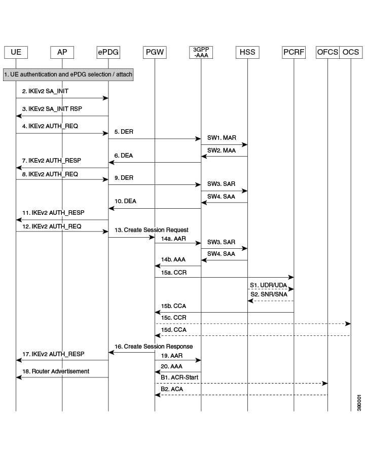
The UE and the ePDG exchange the first pair of messages, known as IKE_SA_INIT and RSP, in which the ePDG and UE negotiate cryptographic algorithms, exchange nonces and perform a Diffie_Hellman exchange.
| Step | Description |
|---|---|
| 1. | The UE sends IKE_SA_INIT Message. |
| 2. | ePDG responds with IKE_SA_INIT_RSP Message. |
| 3. | The UE sends the user identity (in the IDi payload) and the APN information (in the IDr payload) in this first message of the IKE_AUTH phase, and begins negotiation of child security associations. The UE omits the AUTH parameter in order to indicate to the ePDG that it wants to use EAP over IKEv2. The user identity shall be compliant with Network Access Identifier (NAI) format specified in TS 23.003 containing the IMSI, as defined for EAP-AKA in RFC 4187. The UE shall send the configuration payload (CFG_REQUEST) within the IKE_AUTH request message to obtain an IPv4 home IP Address and/or a Home Agent Address. When the MAC ULI feature is enabled, the root NAI used will be of the form „0<IMSI>AP_MAC_ADDR:nai.epc.mnc<MNC>.mcc<MCC>.3gppnetwork.org“. |
| 4. | The ePDG sends the Authentication and Authorization Request message to the 3GPP AAA Server, containing the user identity and APN. |
| 5. | The 3GPP AAA Server shall fetch the user profile and authentication vectors from HSS/HLR (if these parameters are not available in the 3GPP AAA Server). The 3GPP AAA Server shall lookup the IMSI of the authenticated user based on the received user identity (root NAI) and include the EAP-AKA as requested authentication method in the request sent to the HSS. The HSS shall then generate authentication vectors with AMF separation bit = 0 and send them back to the 3GPP AAA server. The 3GPP AAA Server checks in user’s subscription if he/she is authorized for non-3GPP access. The counter of IKE SAs for that APN is stepped up. If the maximum number of IKE SAs for that APN is exceeded, the 3GPP AAA Server shall send an indication to the ePDG that established the oldest active IKE SA (it could be the same ePDG or a different one) to delete the oldest established IKE SA. The 3GPP AAA Server shall update accordingly the information of IKE SAs active for the APN.The 3GPP AAA Server initiates the authentication challenge. The user identity is not requested again. |
| 6. | The ePDG responds with its identity, a certificate, and sends the AUTH parameter to protect the previous message it sent to the UE (in the IKE_SA_INIT exchange). It completes the negotiation of the child security associations if any. The EAP message received from the 3GPP AAA Server (EAP-Request/AKA-Challenge) is included in order to start the EAP procedure over IKEv2. |
| 7. | The UE checks the authentication parameters and responds to the authentication challenge. The only payload (apart from the header) in the IKEv2 message is the EAP message. |
| 8 | The ePDG forwards the EAP-Response/AKA-Challenge message to the 3GPP AAA Server. |
| 8a | The AAA checks, if the authentication response is correct. |
| 9. | When all checks are successful, the 3GPP AAA Server sends the final Authentication and Authorization Answer (with a result code indicating success) including the relevant service authorization information, an EAP success and the key material to the ePDG. This key material shall consist of the MSK generated during the authentication process. When the SWm and SWd interfaces between ePDG and 3GPP AAA Server are implemented using Diameter, the MSK shall be encapsulated in the EAP-Master-Session-Key-AVP, as defined in RFC 4072. |
| 10. | The MSK shall be used by the ePDG to generate the AUTH parameters in order to authenticate the IKE_SA_INIT phase messages, as specified for IKEv2 in RFC 4306. These two first messages had not been authenticated before as there was no key material available yet. According to RFC 4306 [3], the shared secret generated in an EAP exchange (the MSK), when used over IKEv2, shall be used to generated the AUTH parameters. |
| 11. | The EAP Success/Failure message is forwarded to the UE over IKEv2. |
| 12 | The UE takes its own copy of the MSK as input to generate the AUTH parameter to authenticate the first IKE_SA_INIT message. The AUTH parameter is sent to the ePDG. |
| 12a | The ePDG checks the correctness of the AUTH received from the UE. At this point the UE is authenticated. |
| 13 | On successful authentication the ePDG selects the P-GW based on Node Selection options.The ePDG sends Create Session Request (IMSI, [MSISDN], Serving Network, RAT Type (WLAN), Indication Flags, Sender F-TEID for C-plane, APN, Selection Mode, PAA, APN-AMBR, Bearer Contexts, [Recovery], [Charging characteristics], [Additional Protocol Configuration Options (APCO)]), Private IE (P-CSCF, AP MAC address). Indication Flags shall have Dual Address Bearer Flag set if PDN Type is IPv4v6.Handover flag shall be set to Initial or Handover based on the presence of IP addresses in the IPv4/IPv6_Address configuration requests.Selection Mode shall be set to „MS or network provided APN, subscribed verified“. The MSISDN, Charging characteristics, APN-AMBR and bearer QoS shall be provided on S2b interface by ePDG when these are received from AAA on SWm interface.The control plane TEID shall be per PDN connection and the user plane TEID shall be per bearer created. |
| 14. | The P-GW allocates the requested IP address session and responds back to the ePDG with a Create Session Response (Cause, P-GW S2b Address C-plane, PAA, APN-AMBR, [Recovery], Bearer Contexts Created, [Additional Protocol Configuration Options (APCO)], Private IE (P-CSCF)) message. |
| 15. | The ePDG calculates the AUTH parameter which authenticates the second IKE_SA_INIT message |
| 16. | The ePDG sends the assigned Remote IP address in the configuration payload (CFG_REPLY).The AUTH parameter is sent to the UE together with the configuration payload, security associations and the rest of the IKEv2 parameters and the IKEv2 negotiation terminates. |
| 17. | Router Advertisement will be sent for IPv6 address assignments, based on configuration.Note If the ePDG detects that an old IKE SA for that APN already exists, it will delete the IKE SA and send the UE an INFORMATIONAL exchange with a Delete payload in order to delete the old IKE SA in UE. |
Static and Dynamic P-GW Selection
The P-GW selection function enables the ePDG to allocate a P-GW to provide PDN connectivity to the WLAN UEs in the untrusted non-3GPP IP access network. The P-GW selection function can employ either static or dynamic selection.
- Static Selection
- Dynamic Selection
- P-GW Initiated Bearer Modification
- Topology/Weight-based Selection
Static Selection
The PDN-GW-Allocation-Type AVP indicates whether the P-GW address is statically allocated or dynamically selected by other nodes, and is considered only if MIP6-Agent-Info is present. When the PDN-GW-Allocation-Type AVP is absent or is STATIC, and an initial attach occurs, or is DYNAMIC and a handoff attach occurs, the ePDG performs static selection of the P-GW.
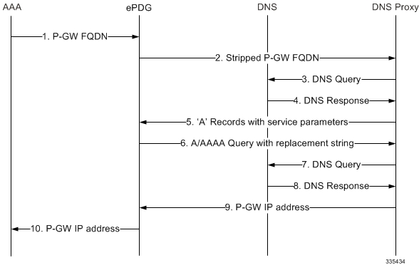
The figure below shows the message exchange for static selection. The table that follows the figure describes each step in the flow.
| Step | Description |
|---|---|
| 1. | The AAA server sends the P-GW FQDN (Fully Qualified Domain Name) to the ePDG. |
| 2. | The ePDG receives the P-GW FQDN from the AAA server as part of the MIP-Home-Agent-Host AVP in a Diameter EAP Answer message.The ePDG removes the first two labels of the received P-GW FQDN (if the FQDN starts with ‚topon‘) to obtain the Canonical Node Name ID of the P-GW. The ePDG uses this P-GW ID to send an S-NAPTR (Server-Name Authority Pointer) query to the DNS proxy. |
| 3. | The DNS proxy send the S-NAPTR query to the DNS. |
| 4. | The DNS may return multiple NAPTR resource records with an ‚A‘ flag (for an address record) with the same or different service parameters. |
| 5. | The DNS proxy forwards the two NAPTR resource records to the ePDG. |
| 6. | The ePDG selects the replacement string (the P-GW FQDN) that matches the service parameter if ePDG is configured as MAG for PMIPv6 protocol or service parameter ‚x-3gpp-pgw:x-s2b-gtp‘ when ePDG is configured for GTP protocol support. The ePDG then performs an A/AAAA query with the selected replacement string (the P-GW FQDN). |
| 7. | The DNS proxy send the A/AAAA query to the DNS. |
| 8. | The DNS returns the IP address of the P-GW. |
| 9. | The DNS proxy forwards the P-GW IP address to the ePDG. |
Dynamic Selection
For a given APN, when the HSS returns Dynamic Allocation Allowed for the P-GW ID and the selection is not for a 3GPP-to-non-3GPP handover, the ePDG ignores the P-GW ID and instead performs dynamic selection.
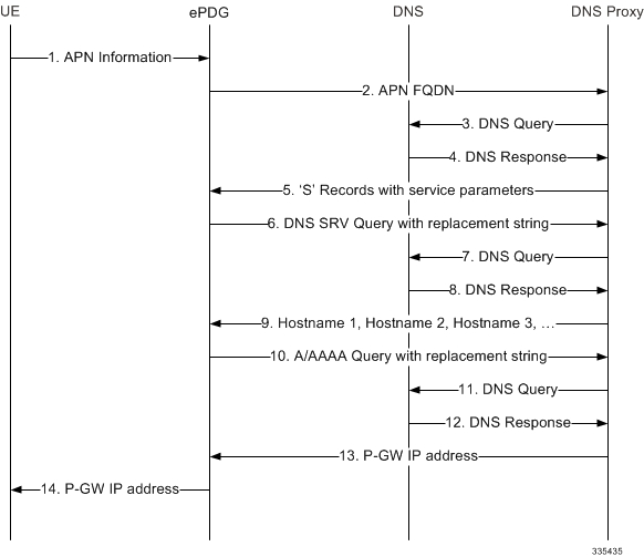
The figure below shows the message exchange for dynamic selection. The table that follows the figure describes each step in the flow.
| Step | Description |
|---|---|
| 1. | The WLAN UE sends the APN name to the ePDG. |
| 2. | The ePDG constructs the APN FQDN from the received APN name. The ePDG uses this query string to send an S-NAPTR (Server-Name Authority Pointer) query to the DNS proxy. |
| 3. | The DNS proxy sends the S-NAPTR query to the DNS. |
| 4. | The DNS may return multiple NAPTR resource records with an ‚S‘ flag (for SRV records) with the same or different service parameters. |
| 5. | The DNS proxy forwards the NAPTR resource records to the ePDG. |
| 6. | The ePDG selects the replacement strings (the APN FQDNs) that matches the service parameter if ePDG is configured as MAG for PMIPv6 protocol or service parameter ‚x-3gpp-pgw:x-s2b-gtp‘ when ePDG is configured for GTP protocol support. The ePDG then performs a DNS SRV query with a replacement string (the APN FQDN) for each of the selected replacement strings. |
| 7. | The DNS proxy sends each DNS SRV query to the DNS. |
| 8. | For each SRV query, the DNS returns the SRV resource records with the target strings. |
| 9. | The DNS proxy forwards the SRV response to the ePDG. The ePDG compares the P-GW FQDNs against the configured ePDG FQDN and selects longest suffix matching entry. |
| 10. | The ePDG performs an A/AAAA query with the selected P-GW FQDN. |
| 11. | The DNS proxy sends the A/AAAA query to the DNS. |
| 12. | The DNS returns the IP address of the P-GW. |
| 13. | The DNS proxy forwards the P-GW IP address to the ePDG. |
P-GW Initiated Bearer Modification
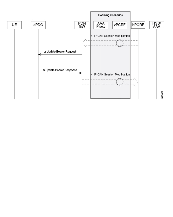
The following section covers the P-GW initiated default/dedicated bearer modification procedure.
| Step | Description |
|---|---|
| 1. | If dynamic PCC is deployed, the PCRF sends a PCC decision provision (QoS policy) message to the PDN GW. This corresponds to the initial steps of the PCRF-Initiated IP CAN Session Modification procedure or to the PCRF response in the PCEF initiated IP-CAN Session Modification procedure, up to the point that the PDN GW requests IP CAN Bearer Signalling. If dynamic PCC is not deployed, the PDN GW may apply local QoS policy. |
| 2. | The PDN GW uses this QoS policy to determine that a service data flow shall be aggregated to or removed from an active S2b bearer or that the authorized QoS of a service data flow has changed. The PDN GW generates the TFT and updates the EPS Bearer QoS to match the traffic flow aggregate. The PDN GW then sends the Update Bearer Request (APN AMBR, Bearer Context (EPS Bearer Identity, EPS Bearer QoS, TFT)) message to the ePDG. |
| 3. | The ePDG uses the uplink packet filter (UL TFT) to determine the mapping of traffic flows to the S2b bearer and acknowledges the S2b bearer modification to the P-GW by sending an Update Bearer Response (EPS Bearer Identity) message. Also the QCI values received in QoS shall be updated and utilized for the UL traffic DSCP mapping/marking. |
Topology/Weight-based Selection
Topology/weight-based selection uses DNS requests to enable P-GW load balancing based on topology and/or weight.
For topology-based selection, once the DNS procedure outputs a list of P-GW hostnames for the APN FQDN, the ePDG performs a longest-suffix match and selects the P-GW that is topologically closest to the ePDG and subscriber. If there are multiple matches with the same suffix length, the Weight and Priority fields in the NAPTR resource records are used to sort the list. The record with the lowest number in the Priority field is chosen first, and the Weight field is used for those records with the same priority.
For weight-based selection, once the DNS procedure outputs a list of P-GW hostnames for the APN FQDN, if there are multiple entries with same priority, calls are distributed to these P-GWs according to the Weight field in the resource records. The Weight field specifies a relative weight for entries with the same priority. Larger weights are given a proportionately higher probability of being selected. The ePDG uses the value of (65535 minus NAPTR preference) as the statistical weight for NAPTR resource records in the same way as the SRV weight is used for SRV records, as defined in RFC 2782.
When both topology-based and weight-based selection are enabled on the ePDG, topology-based selection is performed first, followed by weight-based selection. A candidate list of P-GWs is constructed based on these, and the ePDG selects a P-GW from this list for call establishment. If the selected P-GW does not respond, the ePDG selects the alternate P-GW(s) from the candidate list.
Dual Stack Support
The ePDG supports PDN type IPv4v6. The ePDG handles traffic originating from both IPv4 and IPv6 UE addresses based on configured traffic selectors. Here Dual stack is mentioned for subscriber traffic (inner IP packets).
The ePDG determines the PDN type based on the requested IP address versions sent from the UE in the CP payload (CFG_REQUEST) within the IKE_AUTH Request message. The ePDG sets the IPv6 Home Network Prefix option and IPv4 Home Address Request option parameters when sending the PBU (Proxy-MIP Binding Update) message to the P-GW, specifying the PDN type as IPv4v6. In case the protocol used on S2b is GTPv2 then the ePDG sets the PDN Type inside PAA (PDN Address Allocation) as IPv4v6 and sends the same in Create Session Request Message to the P-GW. The ePDG sends the addresses allocated by the P-GW in the PBA (Proxy-MIP Binding Acknowledgement) / Create Session Response message to the UE via the CP payload (CFG_REPLY) in the IKE_AUTH Response message.
Inter-access Handover Support
The ePDG supports inter-access handovers between two different interfaces, such as a handover between a 3GPP network and an untrusted non-3GPP IP access network, or between two untrusted non-3GPP IP access networks.
When a UE sends an IKE_AUTH Request message with a NULL IPv4/IPv6 address in the CP payload, the ePDG determines that the request is for an initial attach. When a message contains non-null IP address values, the ePDG determines that the request is for a handover attach. On the SWu interface, the UE populates the INTERNAL_IP4_ADDRESS and/or INTERNAL_IP6_ADDRESS parameter with the previously-assigned IP addresses to indicate that UE supports IP address preservation for handovers.
In case the protocol used on S2b is PMIPv6, per 3GPP TS 29.275, the ePDG indicates an inter-access handover in the S2b Handoff Indicator option of PBU (Proxy-MIP Binding Update) messages. Per RFC 5213, the ePDG indicates the RAT (Radio Access Technology) of untrusted non-3GPP access network in the Access Technology Type option.
In case the protocol used on S2b is GTPv2 then per 3GPP TS 29.274, the ePDG indicates an inter-access handover in the indication flags IE.
Mobile Access Gateway Function
The ePDG hosts a MAG (Mobile Access Gateway) function, which acts as a proxy mobility agent in the E-UTRAN/EPC network and uses Proxy Mobile IPv6 signaling to provide network-based mobility management on behalf of the UEs attached to the network. The P-GW also uses Proxy Mobile IPv6 signaling to host an LMA (Local Mobility Anchor) function to provide network-based mobility management. With this approach, the attached UEs are no longer involved in the exchange of signaling messages for mobility.
The MAG function on the ePDG and the LMA function on the P-GW maintain a single shared tunnel. To distinguish between individual subscriber sessions, separate GRE keys are allocated in the PBU (Proxy-MIP Binding Update) and PBA (Proxy-MIP Binding Acknowledgement) messages between the ePDG and the P-GW. If the Proxy Mobile IP signaling contains PCOs (Protocol Configuration Options), it can also be used to transfer P-CSCF or DNS addresses.
The S2b interface uses IPv6 for both control and data. During PDN connection establishment, the P-GW uses Proxy Mobile IPv6 signaling to allocate the IPv6 HNP (Home Network Prefix) to the ePDG, and the ePDG returns the HNP to the UE in an IPv6 router advertisement.
Note that the MAG function on the ePDG does not support multiple PDN connections for the same APN and UE combination. The ePDG establishes each subsequent connection from the same UE to the same APN via a new session and deletes the previous session before the new session gets established.
IPv6 Router Advertisement Support
The ePDG provides router advertisement support for IPv6 and dual stack PDNs to allow the WLAN UEs to initialize the IPv6 protocol stack. The ePDG sends an unsolicited router advertisement to the UE for an IPv6 PDN connection after sending the final IKE_AUTH Response message. When the ePDG receives a Router Solicitation Request message from the UE, the ePDG intercepts the message and responds to it. This is needed for some UEs that perform address auto-configuration despite receiving the IP address information through the CP payload of the IKE_AUTH Response message.
DNS Request Support
During IPSec tunnel establishment, the WLAN UEs can request an IP address for the DNS in the CP payload (CFG_REQUEST). The ePDG retrieves the request from the CFG_REQUEST attribute of the first IKE_AUTH message exchange and includes it in the PBU (Proxy-MIP Binding Update) message sent to the P-GW.
The ePDG sends the PBU message by framing the MIPv6 APCO VSE (Additional Protocol Configuration Options Vendor Specific Extension) with an IPv6 and/or IPv4 DNS request to the P-GW. Once the response is received from the P-GW with the list of IPv6 and/or IPv4 DNS addresses in the returned MIPv6 APCO VSE, the ePDG includes the final address(es) in the CP payload (CFG_REPLY) of the final IKE_AUTH Response message sent to the UE.
In case the Protocol used on S2b is GTPv2 then APCO is used in Create Session Request message for requesting the IPv4 or IPv6 DNS server address request and then P-GW communicates the DNS server addresses in the APCO IE in the Create Session Response Message, the ePDG includes the final address(es) in the CP payload (CFG_REPLY) of the final IKE_AUTH Response message sent to the UE.
Note that the ePDG includes a maximum of two IPv4 DNS addresses and/or a maximum of two IPv6 DNS addresses in the CP payload (CFG_REPLY).
P-CSCF Request Support
To connect to the IMS core network, the WLAN UEs perform P-CSCF discovery as part of session establishment. This feature supports P-CSCF attributes in CFG_REQUEST and CFG_REPLY messages as part of the CP payload in the IKE_AUTH Request and Response messages the ePDG sends and receives from the UEs. The P-CSCF attribute can be sent on SWu as private or with standard value.
The WLAN UEs request a P-CSCF address in IKE_AUTH messages to establish IMS PDN connections. The ePDG receives the P-CSCF attribute in the CP payload (CFG_REQUEST) of the first IKE_AUTH message exchange and includes a P-CSCF Request message in the PBU (Proxy-MIP Binding Update) message to the P-GW. The ePDG sends the PBU message by framing the MIPv6 PCO VSE (Protocol Configuration Options Vendor Specific Extension) within the P-CSCF Request message to the P-GW. Once the ePDG receives the response from the PGW with the list of P-CSCF addresses, the ePDG shall include the P-CSCF addresses in the CP payload (CFG_REPLY) of the final IKE_AUTH Response message sent to the UE.
In case protocol used on S2b is GTPV2 ePDG has flexibility to use either APCO IE or Private Extension IE based on ePDG configuration. Once the ePDG receives the response from the P-GW with the list of P-CSCF addresses in the APCO / Private Extension IE, the ePDG includes the P-CSCF addresses in the CP payload (CFG_REPLY) of the final IKE_AUTH Response message sent to the UE.
On SWu interface the ePDG is able to handle the private attribute value for the P-CSCF address and this private attribute value is configurable on ePDG. By default 16384 is used for P-CSCF IPv4 address and 16390 is used for the IPv6 P-CSCF address. The values 16384-32767 are for private use among mutually consenting parties.
The P-CSCF v4 and v6 are recently assigned values by IANA so ePDG shall be supporting those values as well in addition to the private configured value. ePDG should respond to UE with same attribute value as received in the request. Private values are maintained for the devices which are already in market as they may not comply to standard values.
UE should include P-CSCF_V4_ADDR attribute only once in IKE_AUTH request and no specific P-CSCF address is included because it is a request. ePDG is enhanced to support both IPv4 and IPv6 P-CSCF address handling together. ePDG also supports maximum of 3 IPv4 and 3 IPv6 P-CSCF addresses. The exceeding P-CSCF address will be ignored. In case of invalid P-CSCF address are received the P-CSCF address is ignored and have no impact on the call establishment.
On S2b interface the P-CSCF is enhanced to support both APCO IE and private Extension IE. ePDG continues to use existing „vendor-specific-attribute“ configuration present under epdg-service to decide whether to use APCO IE or private extension IE. The feature scope shall be limited to GTPv2 and shall not cover PMIPv6 as most of the customers are showing interest in GTPv2 based deployment.
Multiple PDN Support
The multiple PDN feature enables the WLAN UEs to simultaneously establish multiple PDN connections towards the P-GW. Each PDN connection has a separate IKE tunnel established between the UE and the ePDG.
Note that the ePDG supports multiple PDN connections to different APNs only and multiple PDN connections from the same UE to the same APN are not allowed. The ePDG establishes each subsequent connection from the same UE to the same APN via a new session and deletes the previous session before the new session gets established. These new PDN connections use different IPSec/PMIPv6/GTPv2 tunnels.
To request a new session, the UE sends the APN information (in the IDr payload) along with the user identity (in the IDi payload) in this first IKE_AUTH Request message, and begins negotiation of Child SAs. The ePDG sends the new APN information in the Service Selection Mobility Option towards the P-GW, which treats each MN-ID+APN combination as a separate binding and allocates a new IP address/prefix for each new binding.
In case of S2b protocol being used as GTPv2 IMSI + APN is used for identifying the unique session.
Default APN Support
The ePDG supports a default APN when APN information is not available from the WLAN UEs over the SWu interface.
When the APN information is received from the WLAN UEs, the information is sent towards the AAA server via DER (Diameter EAP Request) messages. When the APN information is absent, the AAA server provides the default APN to the ePDG in a DEA (Diameter EAP Answer) message.
Congestion Control
The congestion control feature allows you to set policies and thresholds and specify how the system reacts when faced with a heavy load condition.
The congestion control feature monitors the system for conditions that could potentially degrade performance when the system is under heavy load. Typically, these conditions are temporary (for example, high CPU or memory utilization) and are quickly resolved. However, continuous or large numbers of these conditions within a specific time interval may have an impact on the system’s ability to service subscriber sessions. Congestion control helps identify such conditions and invokes policies for addressing the situation.Congestion control operation is based on configuring the following:
- Congestion Condition Thresholds: Thresholds dictate the conditions for which congestion control is enabled and establishes limits for defining the state of the system (congested or clear). These thresholds function in a way similar to operation thresholds that are configured for the system as described in the Thresholding Configuration Guide. The primary difference is that when congestion thresholds are reached, a service congestion policy and an SNMP trap, starCongestion, are generated. A threshold tolerance dictates the percentage under the configured threshold that must be reached in order for the condition to be cleared. An SNMP trap, starCongestionClear, is then triggered.
- Port Utilization Thresholds: If you set a port utilization threshold, when the average utilization of all ports in the system reaches the specified threshold, congestion control is enabled.
- Port-specific Thresholds: If you set port-specific thresholds, when any individual port-specific threshold is reached, congestion control is enabled system-wide.
- Service Congestion Policies: Congestion policies are configurable for each service. These policies dictate how services respond when the system detects that a congestion condition threshold has been crossed. The ePDG supports congestion policies to either drop or reject new calls when congestion is detected in the system.
The congestion control overload disconnect feature can also be enabled for disconnecting passive calls during an overload situation. The ePDG selects passive calls based on the overload disconnect configuration options.
The following table lists the congestion-control threshold command options supported on the ePDG in this release.
| Option | Description |
|---|---|
| license-utilization percent | The percent utilization of licensed session capacity as measured in 10 second intervals.percent can be configured to any integer value from 0 to 100.Default: 100 |
| max-sessions-per-service-utilization percent | The percent utilization of the maximum sessions allowed per service as measured in real time. This threshold is based on the maximum number of sessions or PDP contexts configured for the a particular service.percent can be an integer from 0 through 100.Default: 80 |
| port-rx-utilization percent | The average percent utilization of port resources for all ports by received data as measured in 5 minute intervals.percent can be an integer from 0 through 100.Default: 80 |
| port-specific { slot/port | all } [ rx-utilization percent ] [ tx-utilization percent ] | Sets port-specific thresholds. If you set port-specific thresholds, when any individual port-specific threshold is reached, congestion control is applied system-wide.slot/port: Specifies the port for which port-specific threshold monitoring is being configured. The slot and port must refer to an installed card and port.all: Set port specific threshold monitoring for all ports on all cards.rx-utilization percent: Default 80. The average percent utilization of port resources for the specified port by received data as measured in 5 minute intervals. percent must an integer from 0 through 100.tx-utilization percent: Default 80. The average percent utilization of port resources for the specified port by transmitted data as measured in 5 minute intervals. percent must an integer from 0 through 100.Default: Disabled |
| port-tx-utilization percent | The average percent utilization of port resources for all ports by transmitted data as measured in 5 minute intervals.percent can be an integer from 0 through 100.Default: 80 |
| service-control-cpu-utilization percent | The average percent utilization of CPUs on which a Demux Manager software task instance is running as measured in 10-second intervals.percent can be an integer from 0 through 100.Default: 80 |
| system-cpu-utilization percent | The average percent utilization for all PSC2 CPUs available to the system as measured in 10-second intervals.percent can be an integer from 0 through 100.Default: 80 |
| system-memory-utilization percent | The average percent utilization of all CPU memory available to the system as measured in 10-second intervals.percent can be an integer from 0 through 100.Default: 80 |
Important:
For more information on congestion control, including configuration instructions, see the System Administration Guide. For more information on the congestion-control threshold command, see the eHRPD/LTE Command Line Interface Reference.
Session Recovery Support
Session recovery provides seamless failover and reconstruction of subscriber session information in the event of a hardware or software fault within the system, preventing a fully connected user session from being disconnected. The ePDG supports session recovery for IPv4, IPv6, and IPv4/v6 sessions and ensures that data and control planes are re-established as they were before the recovery procedure.When session recovery occurs, the system reconstructs the following subscriber information:
- Data and control state information required to maintain correct call behavior, including DNS, P-GW, and P-CSCF addresses.
- Subscriber data statistics that are required to ensure that accounting information is maintained.
- A best-effort attempt to recover various timer values, such as call duration, absolute time, and others.
Note that for the recovered sessions, the ePDG recreates counters only and not statistics.
Session recovery is also useful for in-service software patch upgrade activities. If session recovery is enabled during the software patch upgrade, it helps to preserve existing sessions on the active hardware during the upgrade process.Important:
For more information on session recovery support, see the System Administration Guide.
ICSR Support
The ePDG supports ICSR with fault detection and automatic switch over. The subscriber session details for all ePDG interfaces are replicated in stand by, In case of a switchover, the new chassis processes all subsequent control and data traffic for the subscriber session.
The SWu, SWm and S2b interface are not impacted by the switchovers.
ePDG release 18.0 supports upgrade/down grade from release 18 (N) to 16 (N-2).Important:
For more information on ICSR, see the System Administration Guide.
ePDG P-GW selection
The ePDG selects P-GW node based one of the logic:
- eDNS
- DNS over TCP
- P-GW re-selection on session timeout
- PGW re-selection on call attempt failure due to PGW reject
eDNS
The ePDG supports extended DNS client to handle DNS response larger than 512 bytes.
RFC 1035 limits the size of DNS responses over UDP to 512 bytes. If P-GW discovery is done via DNS, there is a chance of 512 byte limit is hit as there are multiple P-GWs supporting an APN consequently having multiple responses to the DNS query, resulting in truncation of the RRs.
Extended the DNS (RFC 2671) allows the client to advertise a bigger re-assemble buffer size to the DNS server so that the server can send a response bigger than 512 bytes. An interim solution to the truncation issue is to arrange the RRs hierarchically so that the limit is never hit.
DNS over TCP
By default DNS client communicates with the server over UDP port. The client can support eDNS, DNS responses up to 4 K Bytes in size from the server. If FQDN resolves too many RRs, the 4 KB limit could be exhausted.
Use the following approach to resolve this issue:
Use TCP port when the server needs to send bigger responses (up to 64 KB), this needs to be driven by the client. When the server indicates that it is not able to send all the answers to a query by setting the truncation bit in the response header. The client on seeing this would switch to TCP port and re-sends the same query. The client continues to use UDP port for new requests.
P-GW re-selection on session timeout
During dynamic P-GW node selection by ePDG, if the selected P-GW is unreachable, the ePDG will select the next P-GW entry from the P-GW candidate list returned during the S-NAPTR procedure to set up the PDN connection.
PGW re-selection on call attempt failure due to PGW reject
ePDG attempts to select alternate PGW when the first PGW has rejected the call with the below error causes. Maximum alternate PGW selection attempts(0-64) can be configured per APN profile using CLI, default is 3.
- EGTP_CAUSE_ALL_DYNAMIC_ADDR_OCCUPIED (0x54)
- EGTP_CAUSE_NO_RESOURCES_AVAILABLE(73)
- EGTP_CAUSE_SERVICE_DENIED (0x59),
- EGTP_CAUSE_PEER_NOT_RESPONDING-(100)
- EGTP_CAUSE_SERVICE_NOT_SUPPORTED (0x44)
S2b GTPv2 support
ePDG supports PDN connection, session establishment and release, along with support for dedicated bearer creation, deletion and modification that is initiated by the P-GW.
During the initial attachment, the ePDG „default EPS QOS“, and „APN-AMBR“ values are populated in the create session request based on the values received from the SWm interface. If these values are missing in the messages received on the SWm interface, ePDG encodes the mandatory or conditional IE with the values set to zero.
When a new PDN connection is established, ePDG allocates and sends a default EPS bearer ID to the PDN gateway. After the initial attach, a default bearer is created for the session, and the IP address is allocated and communicated to the UE.
A GTP-C and GTP-U tunnel is successfully established between the ePDG and P-GW, and an IPSec tunnel is established between the UE and ePDG. Traffic is allowed to flow between these established tunnels.ePDG sends a „delete session request“ message to P-GW, and handles the corresponding „delete session response“ message from the P-GW during the following scenarios:
- UE/ePDG initiated detach with GTP on S2b
- UE requested PDN disconnection with GTP on S2b
- AAA initiated detach with GTP on S2b
ePDG handles the received „create bearer request“ message and sends a „create bearer response“ message for the dedicated bearer creation triggered from the P-GW.
After the dedicated bearer is created, a new GTP-U tunnel is established between ePDG and P-GW, and traffic mapping to the TFT of this bearer occurs. ePDG supports up to 16 packet filters per bearer.
ePDG also stores mapping information between the uplink packet filters received from the P-GW (For example; in the Create Bearer Request message), and the corresponding S2b bearer. ePDG matches these filters and decides if the uplink packets should be allowed or dropped.
ePDG receives the „delete bearer request“ message and sends a „delete bearer response“ message for the dedicated bearer deletion triggered by the P-GW.
ePDG clears the bearer path (GTP-U tunnel) corresponding to the EBI received. In the case of a linked EBI, the PDN connection and its associated bearers are deleted. The TFT mapping for the deleted bearer is also deleted.
ePDG handles the received „update bearer request“ message and sends a „update bearer response“ message for dedicated bearer modification triggered from the P-GW. ePDG updates the UL TFT mapping for the associated bearer using the „bearer context“ information.
ePDG supports path failure detection for control plane by using Echo Request and Echo Response messages. A peer’s IP address-specific counter is reset every time an Echo Response message is received from the peer’s IP address. The counter is incremented when the T3-RESPONSE timer expires for an Echo Request message sent to the peer’s IP address. The path is considered as down if the counter exceeds the value of N3-REQUESTS.
ePDG initiates the Echo requests once retransmission timeout occurs for the request sent to the P-GW. The retransmission for GTP messages is handled by running the retransmission timer (T3-RESPONSE) and for N3-REQUESTS timer, the message is retransmitted after the retransmission timer expires. After all the retransmissions are over, echo handling is initiated.
The GTPC configuration has the configuration command, no gtpc path-failure detection-policy <CR> using which on path failure detection, SNMP traps/alarms are generated notifying that P-GW has gone down, but the sessions are not deleted. The SNMP trap is sent only once per peer, and not for every session. When this command is not configured, path failure detection and the subsequent cleanup action is enabled by default.
Detection of path failure for user plane is supported using the Echo Request/ Echo Response messages. A path counter is reset every time an Echo Response is received and incremented when the T3-RESPONSE timer expires for any Echo Request message sent. The path is considered as down if the counter exceeds the value of N3-REQUESTS.
| Note | By default, path failure detection is not configured for ePDG. |
DSCP and 802.1P Marking
The ePDG can assign DSCP levels to specific traffic patterns in order to ensure that the data packets can be delivered according to the precedence with which they are tagged. The DiffServ markings can be applied to the IP header of the every subscriber data packet transmitted over the SWu and the S2b[GTPv2] interface.
The specific traffic patterns are classified as per their associated QCI/ARP value on the GTP-tunnel. Data packets falling under the category of each of the traffic patterns are tagged with a DSCP marking.
For uplink traffic, i.e. traffic from ePDG to P-GW through GTP tunnel, DSCP markings can be configured using global qci-qos mapping configuration association in ePDG service. In this case, only outer IP header is used for routing the packet over GTP-u‘ interface. Hence TOS field of only outer IP header is changed, i.e. subscriber packet is not marked with DSCP value at ePDG.
ePDG service does have configuration for association of the global configured qci-qos mapping and further in global qci-qos mapping configuration its expected that encaps-header configuration for dscp marking shall be used for setting the TOS value in the outer IP header.
Following is the global configuration under qci-qos mapping:
qci num [ uplink { encaps-header { copy-inner | dscp-marking hex } | 802.1p-value num }]
The 802.1p marking shall be done on the uplink traffic per the qci-qos mapping global configuration corresponding to the map configured under ePDG service. This is similar configuration as described above for DSCP marking.
The 802.1p marking shall be done in the „user priority“ bits of the „TAG“ field in the 802.1q tagged frame.ePDG also supports:
- DSCP marking of Data Packets in uplink (UE->ePDG->PGW) using qci-qos mapping configuration which can be associated to epdg-service
- ePDG marking the inner IP packet DSCP value received from PGW to the outer ESP header in SWu interface
- DSCP marking of Signaling packets (GTPC, on S2b interface) using CLI in egtp-service configuration
- DSCP marking of diameter packets using CLI in Diameter Endpoint configuration
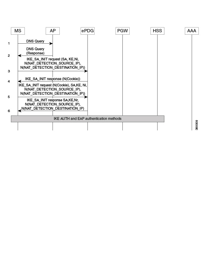
IPSec Cookie Threshold
The ePDG supports IKEv2 Cookie challenge payload, this feature helps protect against opening too many half opened IPSec sessions.
The IKEv2 Cookie feature when enabled will invoke a cookie challenge payload mechanism which ensures that only legitimate subscribers are initiating the IKEv2 tunnel request and not a spoofed attack. Note that this configuration is per ipsecmgr.
The Cookie Challenge mechanism is disabled by default, the number of half open connections over which cookie challenge gets activated is also configurable.Figure 2. IPSec Cookie Threshold
Threshold Crossing Alerts
Thresholding on the system is used to monitor the system for conditions that could potentially cause errors or outages. Typically, these conditions are temporary (high CPU utilization or packet collisions on a network, for example) and are quickly resolved. However, continuous or large numbers of these error conditions within a specific time interval may be indicative of larger, more severe issues. The purpose of thresholding is to help identify potentially severe conditions so that immediate action can be taken to minimize and/or avoid system downtime.
The system supports threshold crossing alerts for certain key resources such as CPU, memory, etc. With this capability, the operator can configure a threshold on these resources whereby, should the resource depletion cross the configured threshold, an SNMP trap would be sent.
The following thresholding models are supported by the system:
- Alert: A value is monitored and an alert condition occurs when the value reaches or exceeds the configured high threshold within the specified polling interval. The alert is generated, then generated and/or sent again at the end of the polling interval.
- Alarm: Both high and low threshold are defined for a value. An alarm condition occurs when the value reaches or exceeds the configured high threshold within the specified polling interval. The alert is generated, then generated and/or sent again at the end of the polling interval.
Thresholding reports conditions using one of the following mechanisms:
- SNMP traps: SNMP traps have been created that indicate the condition (high threshold crossing and/or clear) of each of the monitored values. Generation of specific traps can be enabled or disabled on the chassis, ensuring that only important faults get displayed. SNMP traps are supported in both Alert and Alarm modes.
- Logs: The system provides a facility for which active and event logs can be generated. As with other system facilities, logs are generated messages pertaining to the condition of a monitored value and are generated with a severity level of WARNING. Logs are supported in both the Alert and the Alarm models.
- Alarm System: High threshold alarms generated within the specified polling interval are considered outstanding until a condition no longer exists or a condition clear alarm is generated. Outstanding alarms are reported to the system’s alarm subsystem and are viewable through the Alarm Management menu in the Web Element Manager.
Important:
For more information about threshold crossing alerts, see the Thresholding Configuration Guide.
Bulk Statistics Support
The system’s support for bulk statistics allows operators to choose to view not only statistics that are of importance to them, but also to configure the format in which it is presented. This simplifies the post-processing of statistical data since it can be formatted to be parsed by external, back-end processors.The system can be configured to collect bulk statistics and send them to a collection server called a receiver. Bulk statistics are collected in a group. The individual statistics are grouped by schema. The following is a partial list of supported schema:
- ePDG: Provides statistics to support the ePDG.
- ePDG-APN: Provides statistics to support the ePDG APN level statistics
- System: Provides system-level statistics.
- Card: Provides card-level statistics.
- Port: Provides port-level statistics.
The system supports the configuration of up to four sets of receivers. Each set can have primary and secondary receivers. Each set can be configured to collect specific sets of statistics from the various schema. Bulk statistics can be periodically transferred, based on the transfer interval, using ftp/tftp/sftp mechanisms.
Bulk statistics are stored on the receivers in files. The format of the bulk statistic data files can be configured by the user. Users can specify the format of the file name, file headers, and/or footers to include information such as the date, system host name, system uptime, the IP address of the system generating the statistics (available for headers and footers only), and/or the time that the file was generated.
When the Web Element Manager is used as the receiver, it is capable of further processing the statistics data through XML parsing, archiving, and graphing.
The Bulk Statistics Server component of the Web Element Manager parses collected statistics and stores the information in the PostgreSQL database. If XML file generation and transfer is required, this element generates the XML output and can send it to a northbound NMS or an alternate bulk statistics server for further processing.
Additionally, if archiving of the collected statistics is desired, the Bulk Statistics Server writes the files to an alternative directory on the server. A specific directory can be configured by the administrative user or the default directory can be used. Regardless, the directory can be on a local file system or on an NFS-mounted file system on the Web Element Manager server.Important:
For more information on bulk statistics, see the System Administration Guide.
IKEv2 RFC 5996 Support
StarOS IKEv2 stack currently complies to RFC 4306. In Release 15.0, StarOS IKEv2 is enhanced to comply with newer version of IKEV2 RFC 5996. As part of new version support below features are introduced:
- New notification payloads:RFC 5996 introduces two new notification payloads TEMPORARY_FAILURE and CHILD_SA_NOT_FOUND using which certain conditions of the sender can be notified to the receiver.
- Exchange collisions: ePDG supports collision handling mechanism as defined in RFC 5996, it makes use of the new notify payloads in RFC5996 to do the same. Collision handling can be enabled using CLI, by default. Collision handling is supported as specified in RFC 4306/4718.
- Integrity with combined mode ciphers:StarOS IPSec is enhanced to graciously handle SA payloads containing combined mode cipher. In case an SA payload contains matching payload along with combined mode cipher, the one with combined mode cipher is ignored. Otherwise no proposal chosen is sent.
- Negotiation parameters in CHILDSA REKEY: Negotiation parameters in CHILDSA REKEY: According to RFC 5996 on rekeying of a CHILD SA, the traffic selectors and algorithms match the ones negotiated during the setting up of child SA. StarOS IKEv2 is enhanced to not send any new parameters in CREATE_CHILD_SA for a childsa being rekeyed. However StarOS IKEv2 does not enforce any restrictions on the peer for the same; this is done to minimize impact on IOT’s with existing peer vendor products, which may not be compliant to RFC 5996.
- NAT traversal:The Crypto engine accepts inbound udp-encapsulated IPSec ESP packets even if IKEv2 did not detect NATT. Inbound packets with udp_encap are accepted for processing.
- Certificates:RFC 5996 mandates configurability for sending and receiving HTTP method for hash-and-URL lookup with CERT/CERTREQ payloads. If configured and if peer requests for CERT using encoding type as „Hash and URL of X.509 certificate“ and send HTTP_CERT_LOOKUP_SUPPORTED using notify payload in the first IKE_AUTH, ASR shall send the URL in the CERT payload instead of sending the entire certificate in the payload. If not configured and CERTREQ is received with encoding type as „hash and URL for X.509 certificate“. ASR should respond with entire certificate even if peer had sent HTTP_CERT_LOOKUP_SUPPORTED.
IPv6 Support on IPSec SWU Interface
When a UE attaches to a WiFi Access Point, the WiFi Access Point does assigns the UE an IP Address. Prior to this feature development the IP address assigned was always an IPv4 address. With this feature now the UE shall be provided an IPv4 or IPv6 address by the WiFi Access Point for initiating the IPsec connection to the ePDG over IPv4/IPv6 transport accordingly. For IPv6 transport the IPv6 UDP checksum is mandatory and is supported for IKEv2 establishment.
The ePDG now supports incoming IKEv2 requests from UE over an IPv6 transport as well. One epdg-service can now bound to one IPv4 and IPv6 address which acts as IPsec tunnel endpoint addresses. ePDG continues to support the inner IPv4, IPv6 and IPv4v6 traffic in both IPv4 and IPv6 outer IP SWu transport.
IPv6 NAT support is not standardized and there is no requirement to support the IPv6 NAT . If at all NAT related parameters are present in the crypto template during configuration , it should not have any impact on the tunnel setup and the data flow.
Narrowing Traffic Selectors
During traffic selector negotiation, ePDG by default responds with wildcard IP address, even if the UE is requesting specific range in the TSr. The ePDG should allow to use specific sets of TSs to send traffic to specific sets of address ranges for specific client policies. The ePDG also should respect the range requested by UE and it should (according to the IKEv2 spec) be able to narrow down the UE’s request.IKE Responder performs narrowing As per RFC5996 as shown below:
- If the responder’s policy does not allow it to accept any part of the proposed Traffic Selectors, it responds with a TS_UNACCEPTABLE Notify message.
- If the responder’s policy allows the entire set of traffic covered by TSi and TSr, no narrowing is necessary, and the responder can return the same TSi and TSr values.
- If the responder’s policy allows it to accept the first selector of TSi and TSr, then the responder MUST narrow the Traffic Selectors to a subset that includes the initiator’s first choices.
- If the responder’s policy does not allow it to accept the first selector of TSi and TSr, the responder narrows to an acceptable subset of TSi and TSr.
All these 4 cases will be supported with the exception that at any point of time maximum of four traffic selector per protocol (combination of IPv4 and/or IPv6) will be supported in a single CHILD SA.
When narrowing is done, if there are several subsets are acceptable, GW will respond back with first 4 acceptable subsets and it will not support ADDITIONAL_TS_POSSIBLE notification..
Static IP Address Allocation Support
ePDG supports the static UE IP address communicated by AAA to ePDG over SWm interface (as Served-Party-IP-Address AVP in DEA) and ePDG communicates the same to PGW over S2b interface (as PAA IE of create session request GTP message and Home Network Prefix/IPv4 Home Address in PBU for PMIPv6 case).
This feature is applicable for both GTPv2 and PMIPv6 based implementation.
It shall be AAA server functionality to provide the static PGW IP address, when the UE IP address is provided statically so that same PGW is selected which have the static IP pool corresponding to UE address. ePDG will continue with call establishment and will not be validating the AAA provided PGW allocation type. It is the discretion of PGW to accept/reject call in case the requested static IP address is not available at the PGW.
During handoff calls the priority should be given to UE provided IP address over the ones statically provided by AAA server as the subscribed QoS profile at AAA may not be updated. When UE is offloaded from LTE the IP address provided in LTE to UE should be given priority in WiFi over the AAA provided values. WiFi to WiFi handoff is not a requirement so inter ePDG service handoff is not a valid use-case.
All the three PDN Types UE static IP address are supported including the IPv4, IPv6 and IPv4v6.
| S.N | UE requested PDN Type | AAA provided PDN type | AAA provided Static IP address type | ePDG Action |
|---|---|---|---|---|
| 1 | v4 | v4 | v4 | Call established for v4 PDN type using the AAA provided static IP address. |
| 2 | v4 | v4 | v6 | Call established for v4 PDN type but ignoring the AAA provided IP address. |
| 3 | v4 | v4 | v4v6 | Call established for v4 PDN type and using v4 address provided by AAA. |
| 4 | v4 | v4v6 | v4 | Call established for v4 PDN type and using v4 address provided by AAA. |
| 5 | v4 | v4v6 | v4v6 | Call established for v4 PDN type and using v4 address provided by AAA. |
| 6 | v4 | v4v6 | v6 | Call established for v4 PDN type but ignoring the AAA provided IP address. |
| 7 | v4 | v6 | v6 | Call released due to invalid-pdn-type reason. |
| 8 | v4 | v6 | v4v6 | Call released due to invalid-pdn-type reason. |
| 9 | v4 | v6 | v4 | Call released due to invalid-pdn-type reason. |
| 10 | v6 | v4 | v4v6 | Call released due to invalid-pdn-type reason. |
| 11 | v6 | v4 | v4 | Call released due to invalid-pdn-type reason. |
| 12 | v6 | v4 | v6 | Call released due to invalid-pdn-type reason. |
| 13 | v6 | v6 | v4 | Call established but ignoring the AAA provided IP address. |
| 14 | v6 | v6 | v4v6 | Call established for v6 PDN type and using v6 address provided by AAA and v4 address is ignored. |
| 15 | v6 | v6 | v6 | Call established for v6 PDN type and using v6 address provided by AAA. |
| 16 | v6 | v4v6 | v6 | Call established for v6 pdn and using v6 address provided by AAA. |
| 17 | v6 | v4v6 | v4v6 | Call established for v6 PDN and using v6 address provided by AAA and ignoring the v4 address. |
| 18 | v6 | v4v6 | v4 | Call established but ignoring the AAA provided IP address. |
| 19 | v4v6 | v4 | v6 | Call established using PDN type v4 and the static address provided by AAA is ignored. |
| 20 | v4v6 | v4 | v4 | Call established using PDN type v4 and the static address provided by AAA is used. |
| 21 | v4v6 | v4 | v4v6 | Call established using PDN type v4 and the static address v4 provided by AAA is used. |
| 22 | v4v6 | v6 | v4 | Call established using PDN type v6 and the static address provided by AAA is ignored. |
| 23 | v4v6 | v6 | v6 | Call established using PDN type v6 and the static address provided by AAA is used. |
| 24 | v4v6 | v6 | v4v6 | Call established using PDN type v6 and the static address v6 provided by AAA is used. |
| 25 | v4v6 | v4v6 | v4 | Call established using PDN type v4v6 and static IP address provided by AAA is used. |
| 26 | v4v6 | v4v6 | v6 | Call established using PDN type v4v6 and static v6 IP address provided by AAA is communicated to PGW over S2b. |
| 27 | v4v6 | v4v6 | v4v6 | Call established using PDN type v4v6 and static IP address v4v6 both are communicated to PGW over S2b. |
In case of mismatch in the PDN type between UE requested and the one provided by AAA server the call shall be released by ePDG with „invalid-pdn-type“ as the disconnect reason.
ePDG and PGW Support on the Same Chassis (with GTPv2)
ePDG and PGW services does work together in combo mode (both enabled on the same chassis) with common component resources like IPsec being utilized in best effort manner. Session recovery including card migration is supported for the combo mode
ICSR-VoLTE Support
The ePDG does supports VoLTE call marking when the dedicated bearer corresponding to the QCI configured as VoLTE is created.The VoLTE call does have special handling of allowing data during the ICSR pending standby state and during the ICSR audit phase (at new active) which helps in reducing the data outage for the VoLTE calls during planned ICSR switchover.
Currently, when sessions are created on the ePDG, there is period of 60 seconds (configurable, explained below) lag before the sessions are check-pointed to the standby chassis. If chassis failure occurs during this period, the sessions that were not check-pointed are lost. Also, in some ICSR switchovers, a large number sessions that were not check-pointed need to be flushed resulting in additional delay in the switchover. This causes significant issues for VoLTE service.
This is critical for IMS sessions. If an IMS session is not synchronized with the standby chassis and an ICSR switchover event occurs, the newly active chassis does not have any information of this session and the ePDG is out of sync with other network elements. This situation cannot be corrected until the UE registers again (max 2 hours) and VoLTE calls cannot be delivered to the UE. Therefore, it is critical to minimize the interval in which the session is not synchronized with the peer.
In maintenance mode it’s required that ePDG should automatically delete the VoLTE calls when the VoLTE bearer gets teared down or subscriber becomes non-volte after deletion of all VoLTE bearers.
In earlier release, „clear subs all non-volte“ was implemented to clear non volte calls. Now „clear subs all non-volte auto-del“ shall be implemented to delete non volte calls and mark the volte calls for auto deletion when the volte bearer is torn down. This helps in avoiding manual intervention from admin to cleanup calls again when volte bearer is torn down and the call becomes non-VoLTE. Once the call is marked for auto-deletion it cannot be reverted.
Non VoLTE sessions data outage reduction
ePDG does allows the data for non-VoLTE calls during ICSR switchover to reduce the data-outage for non-VoLTE calls and is configuration controlled to either allow data traffic for both VoLTE and non-VoLTE calls or only VoLTE calls.
Local PGW Resolution Support
In the current implementation of PGW selection, ePDG uses PGW address provided by AAA or uses DNS resolution. With local PGW resolution support, PGW address can be configured locally. If the above two methods (static and dynamic) PGW selection fails, or if PGW address were available but not reachable, then only locally configured addresses are referred and used. Also, if there is no PGW address received from AAA or, if no DNS setup is present, then also locally configured PGW addresses are referred. This way the existing functionality of PGW selection is retained, and added an additional backup-mode with local PGW address configuration resolution.
A new CLI is introduced in ePDG Service Config mode where epdg-service is associated with „subscriber-map“, which is also an indication that „Local PGW Resolution Support“ is enabled for epdg-service. The local PGW resolution will take into effect only if the CLI is configured and none of the existing method of PGW resolution method results in session creation.Below are the Local PGW Resolution Support scenarios:
- PGW address received from AAA, but unreachable
- PGW addresses received by DNS resolution, but all are unreachable
- DNS server is not reachable, or rejects the DNS query
- None of the PGW selection mechanisms(Static/Dynamic) are present, i.e. neither DNS resolution is configured, nor AAA sends any PGW address
In all of the above scenarios, if local PGW address is configured and ePDG-Service is associated with Subscriber-Map, then PGW address is selected based on weight. In this algorithm the sessions are created approximately in the same ratio of the weights configured with the PGW addresses. For example if the weights are 10, 20 and 30, then 1000 sessions will be distributed in ration 1:2:3 respectively. (same algorithm used as DNS resolution based PGW selection mechanism.)
Only first PGW is selected based on weight based selection algorithm and if the call does not gets established with this selected PGW, rest of the addresses are selected on Round Robin method starting from next available PGW configured rounding upto PGW address configured just before the PGW address selected based on weight. This way none of the addresses are repeated. For example if ten PGW address are configured, based on weight 7th one is selected as first address, and if it is unreachable then address at 8th index is selected, then 9th, 10th, 1st, 2nd and so on until address present at 6th index.
In a case where PGW resolution is enabled and the existing DNS/AAA server PGW resolution mechanism failed and there is no disconnect reason already set from previous mechanism, further the local PGW resolution failed due to configuration error then new disconnect reason shall be set „ePDG-local-pgw-resolution-failed“ for identifying the case.
Also in the case of HO, even if the local PGW resolution is enabled and there is no or unreachable PGW address provided by AAA server, or PGW FQDN provided results in no or unreachable PGW address, then ePDG will not use local PGW resolution mechanism for establishing the call.
Local configuration as preferred PGW selection mechanism
The ePDG is further enhanced to support local configuration based PGW selection as the preferred method for PGW node selection.
The ePDG service should be configured indicating preferred method of PGW selection, whether local configuration or DNS/AAA server based PGW selection. Local Configuration based PGW selection as fallback mechanism is default configuration behavior.
This preferred PGW selection mechanism feature provides more control and flexibility to customer for routing/load balancing the sessions on desired PGW.
The feature shall be applicable only for initial attach and for Hand-Off calls ePDG shall use the PGW address provided by AAA server even if the feature is enabled as the PGW selected by local configuration may be different from one have the session on LTE.
Non UICC Device Support Using Certificate Based Authentication
ePDG is enhanced to support the non UICC devices connectivity to EPC via ePDG using certificate based UE authentication following authorization by AAA server.
ePDG already supports UICC devices connectivity using EAP-AKA based device authentication. However as non UICC devices cannot do EAP-AKA based authentication, alternate method of using certificates is used.
ePDG supports the X.509 certificate based authentication and also communicates with OCSP (Online Certificate Status Protocol) server for completing the authentication. Once the authentication is done ePDG communicates with AAA server for ensuring the authorization of the device.
As non UICC devices do not have IMSI, customized vIMSI in format similar to UICC IMSI uniquely identifying the non UICC device needs to be shared by the device. The device IMSI is shared as part of peer (device) certificate to ePDG. ePDG extracts serial number, issuing authority and OCSP responder address details from the certificate and communicates with OCSP responder. In case the OCSP responder detail is absent in the certificate the ePDG configuration is used for extracting the same. The OCSP client (ePDG) to the OCSP responder interaction will be over HTTP. A TCP socket connection will be established to the OCSP responder. OCSP responder communicates with the associated CA (certification authority) and gets the certificate revocation status which can be „good“ or „revoked“ or „unknown“. The ePDG behavior in case of „unknown“ is similar to „revoked“. When the OCSP response reaches ePDG, it validates if the response is received from genuine entity and post validation checks the certificate status. If the certificate status is good then proceeds with device authorization.
ePDG expects the SUBJECT/CN field of UE certificate to contain the IMSI or NAI and detects that its NAI with presence of “ else its IMSI. This extracted CN fields is accordingly verified with the IDi payload received from UE in IKE_AUTH_REQ message. The certificate identity is more reliable and also the IKE_AUTH_REQ identity does have significance is AUTH payload verification hence this functionality of comparison is in place. ePDG sends the NAI identity as received in the IKE_AUTH_REQ message to the AAA server and once AAA server sends back the authorization success then ePDG does PGW selection and communicates with PGW over S2b interface to establish the call.
IPsec subsystem does comply with RFC 2560 and uses open SSL 0.9.7 for certificate based authentication, therefore ePDG inherently complies with same.
ePDG supports both UICC and non-UICC devices simultaneously for same ePDG service. ePDG service does have single crypto template association with the service IP address and hence IPsec subsystem is enhanced for supporting the multiple authentication methods per crypto template. ePDG identifies whether certificate based authentication needs to be used or not by the presence of AUTH payload. If the AUTH parameter is absent in initial IKE_AUTH_REQ message it indicates that EAP-AKA based authentication is to be used. If the AUTH payload is present and the CERT payload is also present it indicates certificate based mechanism is to be used.
OCSP communication is optional and if not configured then ePDG validates based on the configured CA certificates.Figure 3. NON UICC device Call flow
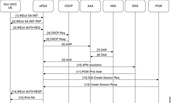
- UE ePDG: IKEv2 SA_INIT UE sends IKE_SA_INIT Request (SA, KE, Ni, NAT-DETECTION Notify).
- ePDG UE: IKEv2 SA_INIT RSP The ePDG responds with an IKE_SA_INIT Response (SA, KE, Nr payloads, NAT-Detection Notify, [CERTREQ]).
- UE ePDG: IKEv2 AUTH_REQ UE sends IKE_AUTH_REQ (IDi, AUTH, CERT, [CERTREQ], IDr, SA, CP (CFG_REQUEST (INTERNAL_IP6_ADDRESS, [INTERNAL_IP6_DNS], [INTERNAL_IP6_PCSCF]), TSi, TSr)). The UE does include AUTH and CERT payload to indicate that it will use the certificates (X.509) for authenticating itself. Presence of AUTH payload indicates EAP-AKA is not used. IDi contains the NAI and IDr does contain the APN name. Root NAI is of format X<IMSI> nai.epc.mnc<MNC>.mcc<MCC>.3gppnetwork.org so IMSI (virtual IMSI used for non UICC device IMSI) is required which should be of decimal digit UICC IMSI format. One proposed approach is to use <device prefix><MSISDN> where MSISDN is common for the associated non UICC and UICC devices but its operator decision and ePDG shall be able to handle it until its unique per non UICC device and is in UICC IMSI format. The certificate SUBJECT/CN field shall be containing the IMSI or NAI as it’s identifier. ePDG uses received public key as part of certificates for authenticating the UE. OCSP shall be used for checking the revocation status during the certificates based device authentication. OCSP communication is optional means if the OCSP responder is absent in operator infrastructure then the ePDG shall be authenticating the device using the configured Root CA certificate.Note :The device can share the certificates (X.509) or can communicate the URL to ePDG for downloading the device certificates. Both the mechanism are supported on ePDG.
- ePDG OCSP responder : OCSP request ePDG sends the OCSP request containing the certificate identifier.
- OCSP responder ePDG :OCSP Response OCSP responder checks and returns back the revocation status of the certificate. At this stage ePDG completes the authentication of the device.
- ePDG AAA server :AAR The ePDG sends the AA-Request (Session-Id, Auth-Application-Id, Origin-Host, Origin-Realm, Destination-Host, Destination-Realm, Auth-Request-Type (AUTHORIZE_AUTHENTICATE), User-Name (NAI)) message to the 3GPP AAA server. ePDG communicates the NAI for AAA to check UE identity and authorize the same.
- AAA server HSS :SAR The 3GPP AAA updates the HSS with the 3GPP AAA Server Address information for the user. The AAA sends Server-Assignment-Request (Session-Id, Auth-Session-State (NO_STATE_MAINTAINED), Origin-Host, Origin-Realm, Destination-Host, Destination-Realm, User-Name (IMSI-NAI), Server-Assignment-Type (REGISTRATION)). Note :As this call flow is not defined in 3GPP yet so the proposed message between AAA to HSS is to be decided by AAA and HSS vendors however based on existing SWx interface messages have proposed the usage of SAR.
- HSS AAA server :SAA The HSS sends Server-Assignment-Answer (Session-Id, Result-Code, Experimental-Result (Vendor-Id, Experimental-Result-Code), Non-3GPP-User-Data {Subscription-ID (END_USER_E164, MSISDN), Non-3GPP-IP-Access (NON_3GPP_SUBSCRIPTION_ALLOWED), Non-3GPP-IP-Access-APN (Non_3GPP_APNS_ENABLE), APN-Configuration , ANID (WLAN)}, APN-OI-Replacement, APN-Configuration})
- AAA server ePDG: AA-Answer The 3GPP AAA Server responds with AAA (Session-Id, Auth-Application-Id, Auth-Request-Type, Origin-Host, Origin-Realm, Result-Code, User-Name, APN-Configuration, 3GPP-Charging-Characteristics, Subscription-ID)
- ePDG DNS server: DNS(NAPTR/AAAA) query ePDG sends DNS query to DNS server with APN/PGW FQDN for PGW resolution.
- DNS server ePDG:DNS query response DNS server returns the PGW address to ePDG as part of DNS AAAA/A response.
- ePDG PGW: S2b Create Session Req ePDG selects PGW based on DNS mechanism using APN/PGW FQDN. The ePDG sends Create Session Request (IMSI, [MSISDN],Serving Network, RAT Type (WLAN), Indication Flags, Sender F-TEID for C-plane, APN, Selection Mode, PAA, APN-AMBR, [APCO], Bearer Contexts(), [Recovery], [Private IE (P-CSCF)]). Selection Mode shall be set to „MS or network provided APN subscribed verified“. Private IE is populated if the UE request P-CSCF addresses. The PGW performs the necessary interactions with 3GPP-AAA, PCRF and OCS/OFCS.
- PGW ePDG: Create Session Resp The PGW allocates the requested IP address session and responds back to the ePDG with a Create Session Response (Cause, PGW S2b F-TEID, PAA, [APN-AMBR],[APCO],Bearer Contexts Created (EPS Bearer ID, Cause, [TFT], S2b-U PGW F-TEID, Bearer Level QoS), [Recovery], [Private IE (P-CSCF)]) message.
- ePDG UE: IKEv2 AUTH_RESP ePDG sends IKE_AUTH_RESP (AUTH, IDr, [CERT (X509 CERTIFICATE SIGNATURE)], CP, SA, CFG_REPLY ([INTERNAL_IP4_ADDRESS], [INTERNAL_IP4_NETMASK], [INTERNAL_IP4_DNS], INTERNAL_IP6_ADDRESS, INTERNAL_IP6_SUBNET, INTERNAL_IP6_DNS, [P-CSCF]) TSi, TSr)
- ePDG UE: IPv6 RA The assumption is that the IP stack needs the RA to initialize the address.
EAP-MSCHAPv2/EAP-TLS/EAP-TTLS Based Support For NON UICC Devices
Currently 3GPP standard provides a mechanism for the UICC (SIM based) devices connectivity to the EPC via non-3GPP access enabling them for voice and video services over WiFi. However lot of non UICC devices such as iPads, Tablets, Laptops do not have defined 3GPP standard mechanism for connecting over WLAN to EPC via ePDG. These devices can use the same LTE subscription as for the UICC device do not have potential to utlize CSPs and monetize voice and video offering by extending the same to non UICC devices.
EAP-AKA is the mechanism defined in 3GPP standards for authenticating and authorizing the mobile devices using AAA server. The non UICC devices cannot support EAP-AKA.
For non UICC devices as IMSI is not present the IMSI mentioned in below flows is vIMSI which can be alphanumeric type (limit to 24 chars) or decimal digit IMSI and in such case when alphanumeric vIMSI is used its expected that AAA server shall be providing decimal digit IMSI to ePDG for S2b interface as part of mobile-node-identifier AVP.Below is the list of different authentication mechanisms which can be used with ePDG acting as EAP pass-through mode for the non UICC device support:
- EAP-MSCHAPv2
- Single phase
- Use MSCHAPv2 inside EAP
- Challenge/Response based mechanism
- Reference – http://tools.ietf.org/id/draft-kamath-pppext-eap-mschapv2-01.txt and RFC 3079
- EAP-TTLS (using MS-CHAPv2)
- EAP method encapsulating TLS session
- Two phases
- Handshake phase (server authentication and key generation)
- Data Phase (client authentication)
- Handshake phase provides secure channel for data phase
- Use MSCHAPv2 for authenticating client/device
- Reference – RFC 5281
- EAP-TLS
- Single phase
- EAP method encapsulating TLS session
- Use certificates between UE and AAA server for mutual authentication
- Reference – RFC 5216
EAP-MSCHAPv2 authentication mechanism call flow
In this authentication mechanism the ePDG shall be acting in EAP pass-through mode and the AAA server shall be authenticating the device using EAP-MSCHAPv2. The authentication mechanism does have advantage of less lengthy call flow and is standard way. Additionally the operator does not require having certificate based infrastructure. The disadvantage is that MSK is 64 bytes but with 32 byte key and remaining 32 bytes as zeros as opposed to EAP-AKA where we have 64 byte non zero MSK. So effectively weaker authentication mechanism key.The Following diagram shows the call flow for the EAP-MSCHAPv2 based authentication:Figure 4. EAP-MSCHAPv2 flow
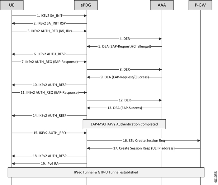
- UE ePDG: IKEv2 SA_INIT UE (UICC based) sends IKE_SA_INIT Request (SA, KE, Ni, NAT-DETECTION Notify).
- ePDG UE: IKEv2 SA_INIT RSP The ePDG responds with an IKE_SA_INIT Response (SA, KE, Nr payloads, NAT-Detection Notify).
- UE ePDG: IKEv2 AUTH_REQ UE sends IKE_AUTH_REQ (IDi, [CERTREQ], IDr, SA, CP (CFQ_REQUEST (INTERNAL_IP6_ADDRESS, [INTERNAL_IP6_DNS], [INTERNAL_IP6_PCSCF]), TSi, TSr)). The UE does not include AUTH payload to indicate that it will use the EAP-MSCHAPv2 method for authenticating itself to AAA. IDi contains the NAI in the form „A<IMSI> nai.epc.mnc<MNC>.mcc<MCC>.3gppnetwork.org“. Per standards the prefix can be 0/1 indicating EAP-AKA/EAP-SIM now as we shall be indicating to AAA server that use different authentication method here EAP-MSCHAPv2 so can indicate using „A“. ePDG shall be transparent to received prefix and shall send to AAA server so that operator is free to use any prefix except the defined ones.
- ePDG AAA server :DER The ePDG sends the DER (Session-Id, Auth-Application-Id, Origin-Host,Origin-Realm, Destination-Host, Destination-Realm, Auth-Request-Type(AUTHORIZE_AUTHENTICATE), EAP-Payload, User-Name (NAI), RAT-Type (WLAN), MIP6-Feature-Vector, Visited-Network-Identifier) message to the 3GPP AAA Server. The EAP-Payload shall contain the UE identity encoded by ePDG.
- AAA server ePDG: DEA The 3GPP AAA Server initiates the authentication challenge and responds with DEA (Session-Id, Base AVPs, Auth-Request-Type and EAP-Payload). The EAP-Payload shall contain the Challenge packet which is used to begin the EAP MS-CHAP-V2 protocol.
- ePDG UE: IKEv2 AUTH_RESP ePDG sends IKE_AUTH_RESP (IDr, [CERT (X509 CERTIFICATE SIGNATURE)], EAP Payload) The IDr is the identity of the ePDG and if the UE requests for certificates then CERT is included. The EAP message received from the 3GPP AAA Server (EAP-Request/Challenge) is included in order to start the EAP procedure over IKEv2.
- UE ePDG: IKEv2 AUTH_REQ The UE sends EAP message in IKE_AUTH Request (EAP) with user-name, MS-CHAP2- Response AVPs.The EAP message shall be of EAP-Type=EAP-MS-CHAP-V2(Response).
- ePDG AAA server :DER The ePDG sends the DER (Session-Id, Auth-Application-Id, Origin-Host, Origin-Realm, Destination-Host, Destination-Realm, Auth-Request-Type (AUTHORIZE_AUTHENTICATE), EAP-Payload) message to the 3GPP AAA Server. The EAP-Payload shall contain the message as sent by UE.
- AAA server ePDG: DEA The 3GPP AAA Server on successful authentication responds with DEA (Session-Id, Base AVPs, Auth-Request-Type and EAP-Payload)
- ePDG UE: IKEv2 AUTH_RESP ePDG sends IKE_AUTH_RESP (EAP Payload) The EAP payload shall contain the EAP-MSCHAPv2 message as received from the AAA server.
- UE ePDG: IKEv2 AUTH_REQ The UE sends IKE_AUTH Request (EAP) with EAP-MSCHAPv2 „Success Response packet“. UE successfully validates the EAP MS-CHAP-V2 Success Request packet sent by the AAA server, respond.
- ePDG AAA server :DER The ePDG sends the DER (Session-Id, Auth-Application-Id, Origin-Host, Origin-Realm, Destination-Host, Destination-Realm, Auth-Request-Type(AUTHORIZE_AUTHENTICATE), EAP-Payload) message to the 3GPP AAA Server. The EAP-Payload shall contain the message as sent by UE.
- AAA server ePDG: DEA The 3GPP AAA Server sends an EAP success (Session-Id, Auth-Application-Id: 16777264, Result-Code, Origin-Host, Origin-Realm, Auth-Request-Type(AUTHORIZE_AUTHENTICATE), EAP-Payload User-Name(0<IMSI>mnc<mnc val>.mcc<mcc val>.pub.3gppnetwork.org), EAP-Master-Session-Key, APN-Configuration (Context-Identifier, PDN-Type: IPv4v6, Service-Selection (apn name), MIP6-Agent-Info), Auth-Session-State: STATE_MAINTAINED, Origin-State-Id). At this point mutual authentication is done and device is authorized by AAA server. The MSK can be generated by AAA server using following logic however ePDG is transparent to MSK generation logic and till the devices and AAA server are in sync any other logic of MSK generation should also work. MSK = MasterReceiveKey + MasterSendKey + 32 bytes zeroes (padding) Note – Extensible Authentication Protocol Method for Microsoft CHAP derives two 16-byte keys, MasterSendKey and MasterReceiveKey (as specified in [RFC3079], section 3.3).
- ePDG UE: IKEv2 AUTH_RESP ePDG sends IKE_AUTH_RESP (EAP Payload) The EAP payload shall contain the EAP-MSCHAPv2 message as received from the AAA server.
- UE ePDG: IKEv2 AUTH_REQ UE sends IKE_AUTH request (AUTH) The UE takes its own copy of the MSK as input to generate the AUTH parameter to authenticate the first IKE_SA_INIT message.
- ePDG PGW: S2b Create Session Req ePDG sends Create Session Request (IMSI, [MSISDN],Serving Network, RAT Type (WLAN), Indication Flags, Sender F-TEID for C-plane, APN, Selection Mode, PAA, APN-AMBR, [APCO], Bearer Contexts(), [Recovery], [Private IE (P-CSCF)]). Selection Mode shall be set to „MS or network provided APN subscribed verified“. The PGW performs the necessary interactions with 3GPP-AAA, PCRF and OCS/OFCS. ePDG shall set the HO in Indication flags IE and also the preserved IP address as received from UE in PAA IE.
- PGW ePDG: Create Session Resp The PGW allocates the requested IP address session and responds back to the ePDG with a Create Session Response (Cause, PGW S2b F-TEID, PAA, [APN-AMBR],APCO, Bearer Contexts Created (EPS Bearer ID, Cause, [TFT], S2b-U PGW F-TEID, Bearer Level QoS), [Recovery], [Private IE (P-CSCF)]) message.
- ePDG UE: IKEv2 AUTH_RESP ePDG sends IKE_AUTH_RESP (AUTH, CP, SA, CFG_REPLY ([INTERNAL_IP4_ADDRESS], [INTERNAL_IP4_NETMASK], [INTERNAL_IP4_DNS], INTERNAL_IP6_ADDRESS, INTERNAL_IP6_SUBNET, INTERNAL_IP6_DNS, [P-CSCF]) TSi, TSr) At this stage the ePDG has completed the ipsec SA and tunnel setup and also GTP-U tunnel setup thus completing the data path. The IP address provided by PGW is communicated to UE.
- ePDG UE: IPv6 RA The assumption is that the IP stack needs the RA to initialize the address.
EAP-TLS authentication mechanism Call Flow
In this mechanism it’s assumed that the authenticator entity shall be AAA server supporting the certificate based authentication. The ePDG shall be acting in EAP pass-through mode thus communicating the EAP-TLS negotiation between device and AAA server. The AAA server once completing the authentication mechanism shall be sharing the MSK to ePDG for generating the AUTH parameters and completing the IKEv2 authentication. Following diagram shows the call flow for the EAP-TLS based authentication:Figure 5. IPsec Based EAP-TLS Flow
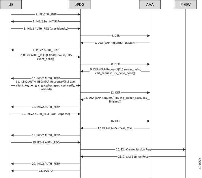
- UE ePDG: IKEv2 SA_INIT UE (UICC based) sends IKE_SA_INIT Request (SA, KE, Ni, NAT-DETECTION Notify).
- ePDG UE: IKEv2 SA_INIT RSP The ePDG responds with an IKE_SA_INIT Response (SA, KE, Nr payloads, NAT-Detection Notify).
- UE ePDG: IKEv2 AUTH_REQ UE sends IKE_AUTH_REQ (IDi, [CERTREQ], IDr, SA, CP (CFQ_REQUEST (INTERNAL_IP6_ADDRESS, [INTERNAL_IP6_DNS], [INTERNAL_IP6_PCSCF]), TSi, TSr)). The UE does not include AUTH payload to indicate that it will use the EAP-TLS method for authenticating itself to AAA. IDi contains the NAI in the form „A<IMSI> nai.epc.mnc<MNC>.mcc<MCC>.3gppnetwork.org“. Per standards the prefix can be 0/1 indicating EAP-AKA/EAP-SIM now as we shall be indicating to AAA server that use different authentication method here EAP-TLS so can indicate using „A“. ePDG shall be transparent to received prefix and shall send to AAA server so that operator is free to use any prefix except the defined ones.
- ePDG AAA server :DER The ePDG sends the DER (Session-Id, Auth-Application-Id, Origin-Host, Origin-Realm, Destination-Host, Destination-Realm, Auth-Request-Type(AUTHORIZE_AUTHENTICATE), EAP-Payload, User-Name (NAI), RAT-Type(WLAN), MIP6-Feature-Vector, Visited-Network-Identifier) message to the3GPP AAA Server. The EAP-Payload shall contain the UE identity encoded by ePDG.
- AAA server ePDG: DEA The 3GPP AAA Server initiates the authentication challenge and responds with DEA (Session-Id, Base AVPs, Auth-Request-Type and EAP-Payload). The EAP-Payload shall contain the EAP-TLS/Start, the Start ‚S‘ bit is set with no data.
- ePDG UE: IKEv2 AUTH_RESP ePDG sends IKE_AUTH_RESP (IDr, [CERT (X509 CERTIFICATE SIGNATURE)], EAP Payload) The IDr is the identity of the ePDG and if the UE requests for certificates then CERT is included. The EAP message received from the 3GPP AAA Server (EAP-Request/Start) is included in order to start the EAP procedure over IKEv2.
- UE ePDG: IKEv2 AUTH_REQ UE sends IKE_AUTH_REQ (EAP payload) containing the TLS client hello handshake message.
- ePDG AAA server :DER The ePDG sends the DER (Session-Id, Auth-Application-Id, Origin-Host, Origin-Realm, Destination-Host, Destination-Realm, Auth-Request-Type(AUTHORIZE_AUTHENTICATE), EAP-Payload, User-Name (NAI), RAT-Type(WLAN), MIP6-Feature-Vector, Visited-Network-Identifier) message to the 3GPP AAA Server. The EAP-Payload shall contain the TLS client hello handshake message.
- AAA server ePDG: DEA The 3GPP AAA Server initiates the authentication challenge and responds with DEA (Session-Id, Base AVPs, Auth-Request-Type and EAP-Payload). The AAA server will then respond with an EAP-Request packet with EAP-Type=EAP-TLS. The data field of this packet will encapsulate one or more TLS records. These will contain a TLS server_hello handshake message, possibly followed by TLS certificate, server_key_exchange, certificate_request, server_hello_done and/or finished handshake messages, and/or a TLS change_cipher_spec message.
- ePDG UE: IKEv2 AUTH_RESP ePDG sends IKE_AUTH_RESP (EAP Payload) The EAP payload shall contain the TLS message as received from the AAA server.
- UE ePDG: IKEv2 AUTH_REQ The UE sends EAP message in IKE_AUTH Request (EAP). The data field of this packet MUST encapsulate one or more TLS records containing a TLS client_key_exchange, change_cipher_spec, and finished messages.
- ePDG AAA server :DER The ePDG sends the DER (Session-Id, Auth-Application-Id, Origin-Host,Origin-Realm, Destination-Host, Destination-Realm, Auth-Request-Type(AUTHORIZE_AUTHENTICATE), EAP-Payload) message to the 3GPP AAA Server. The EAP-Payload shall contain the message as sent by UE.
- AAA server ePDG: DEA The 3GPP AAA Server on successful authentication responds with DEA (Session-Id, Base AVPs, Auth-Request-Type and EAP-Payload) where EAP-Payload does contain the TLS finished message.
- ePDG UE: IKEv2 AUTH_RESP ePDG sends IKE_AUTH_RESP (EAP Payload) The EAP payload shall contain the TLS message as received from the AAA server.
- UE ePDG: IKEv2 AUTH_REQ The UE sends EAP message in IKE_AUTH Request (EAP) with no data.
- ePDG AAA server :DER The ePDG sends the DER (Session-Id, Auth-Application-Id, Origin-Host, Origin-Realm, Destination-Host, Destination-Realm, Auth-Request-Type (AUTHORIZE_AUTHENTICATE), EAP-Payload) message to the 3GPP AAA Server. The EAP-Payload shall contain the message as sent by UE.
- AAA server ePDG: DEA The 3GPP AAA Server sends an EAP success (Session-Id, Auth-Application-Id: 16777264, Result-Code, Origin-Host, Origin-Realm, Auth-Request-Type(AUTHORIZE_AUTHENTICATE), EAP-Payload User-Name(0<IMSI>mnc<mnc val>.mcc<mcc val>.pub.3gppnetwork.org), EAP-Master-Session-Key, APN-Configuration (Context-Identifier, PDN-Type: IPv4v6, Service-Selection (apn name), MIP6-Agent-Info), Auth-Session-State:STATE_MAINTAINED, Origin-State-Id). At this point device is authenticated and authorized by AAA server.
- ePDG UE: IKEv2 AUTH_RESP ePDG sends IKE_AUTH_RESP (EAP Payload) The EAP payload shall contain the TLS message as received from the AAA server.
- UE ePDG: IKEv2 AUTH_REQ UE sends IKE_AUTH request (AUTH) The UE takes its own copy of the MSK as input to generate the AUTH parameter to authenticate the first IKE_SA_INITmessage.
- ePDG PGW: S2b Create Session Req ePDG sends Create Session Request (IMSI, [MSISDN],Serving Network, RAT Type (WLAN), Indication Flags, Sender F-TEID for C-plane, APN, Selection Mode, PAA, APN-AMBR, [APCO], Bearer Contexts(), [Recovery], [Private IE (P-CSCF)]). Selection Mode shall be set to „MS or network provided APN subscribed verified“. The PGW performs the necessary interactions with 3GPP-AAA, PCRF and OCS/OFCS. ePDG shall set the HO in Indication flags IE and also the preserved IP address as received from UE in PAA IE.
- PGW ePDG: Create Session Resp The PGW allocates the requested IP address session and responds back to the ePDG with a Create Session Response (Cause, PGW S2b F-TEID, PAA, [APN-AMBR],APCO, Bearer Contexts Created (EPS Bearer ID, Cause, [TFT], S2b-U PGW F-TEID, Bearer Level QoS), [Recovery], [Private IE (P-CSCF)]) message.
- ePDG UE: IKEv2 AUTH_RESP ePDG sends IKE_AUTH_RESP (AUTH, CP, SA, CFG_REPLY([INTERNAL_IP4_ADDRESS], [INTERNAL_IP4_NETMASK],[INTERNAL_IP4_DNS], INTERNAL_IP6_ADDRESS, INTERNAL_IP6_SUBNET, INTERNAL_IP6_DNS, [P-CSCF]) TSi, TSr) At this stage the ePDG has completed the ipsec SA and tunnel setup and also GTP-U tunnel setup thus completing the data path. The IP address provided by PGW is communicated to UE.
- ePDG UE: IPv6 RA The assumption is that the IP stack needs the RA to initialize the address.
EAP-TTLS authentication mechanism Call Flow
The EAP-TTLS based approach is useful when there is no certificate based infrastructure present for the operator to configure certificate for each device. Unlike EAP-TLS it enables the device authentication without certificates using customized AVPs. Here we have defined MSCHAPv2 based authentication mechanism. Here the AAA server needs to provide the key similar to MSK to ePDG for validating/generating the AUTH payload during IKEv2 xchg. Following diagram shows the call flow for the EAP-TTLS based authentication:Figure 6. IPsec EAP-TTLS MSCHAPv2 Flow
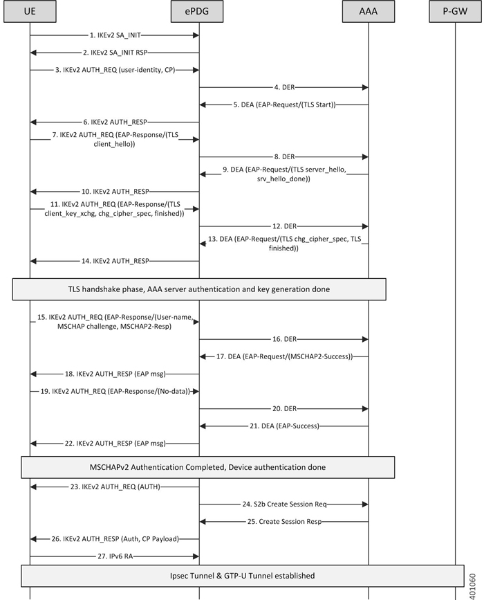
- UE ePDG: IKEv2 SA_INIT UE (UICC based) sends IKE_SA_INIT Request (SA, KE, Ni, NAT-DETECTION Notify).
- ePDG UE: IKEv2 SA_INIT RSP The ePDG responds with an IKE_SA_INIT Response (SA, KE, Nr payloads, NAT-Detection Notify).
- UE ePDG: IKEv2 AUTH_REQ UE sends IKE_AUTH_REQ (IDi, [CERTREQ], IDr, SA, CP (CFQ_REQUEST (INTERNAL_IP6_ADDRESS, [INTERNAL_IP6_DNS], [INTERNAL_IP6_PCSCF]), TSi, TSr)). The UE does not include AUTH payload to indicate that it will use the EAP-TTLS method for authenticating itself to AAA. IDi contains the NAI in the form „A<IMSI> nai.epc.mnc<MNC>.mcc<MCC>.3gppnetwork.org“. Per standards the prefix can be 0/1 indicating EAP-AKA/EAP-SIM now as we shall be indicating to AAA server that use different authentication method here EAP-TTLS so can indicate using „A“. ePDG shall be transparent to received prefix and shall send to AAA server so that operator is free to use any prefix except the defined ones.
- ePDG AAA server :DER The ePDG sends the DER (Session-Id, Auth-Application-Id, Origin-Host, Origin-Realm, Destination-Host, Destination-Realm, Auth-Request-Type(AUTHORIZE_AUTHENTICATE), EAP-Payload, User-Name (NAI), RAT-Type(WLAN), MIP6-Feature-Vector, Visited-Network-Identifier) message to the 3GPP AAA Server. The EAP-Payload shall contain the UE identity encoded by ePDG.
- AAA server ePDG: DEA The 3GPP AAA Server initiates the authentication challenge and responds with DEA (Session-Id, Base AVPs, Auth-Request-Type and EAP-Payload). The EAP-Payload shall contain the EAP-TTLS/Start, the Start ‚S‘ bit is set with no data.
- ePDG UE: IKEv2 AUTH_RESP ePDG sends IKE_AUTH_RESP (IDr, [CERT (X509 CERTIFICATE SIGNATURE)], EAP Payload) The IDr is the identity of the ePDG and if the UE requests for certificates then CERT is included. The EAP message received from the 3GPP AAA Server (EAP-Request/Start) is included in order to start the EAP procedure over IKEv2.
- UE ePDG: IKEv2 AUTH_REQ UE sends IKE_AUTH_REQ (EAP payload) containing the TLS client hello handshake message.
- ePDG AAA server :DER The ePDG sends the DER (Session-Id, Auth-Application-Id, Origin-Host, Origin-Realm, Destination-Host, Destination-Realm, Auth-Request-Type(AUTHORIZE_AUTHENTICATE), EAP-Payload, User-Name (NAI), RAT-Type(WLAN), MIP6-Feature-Vector, Visited-Network-Identifier) message to the 3GPP AAA Server. The EAP-Payload shall contain the TLS client hello handshake message.
- AAA server ePDG: DEA The 3GPP AAA Server initiates the authentication challenge and responds with DEA (Session-Id, Base AVPs, Auth-Request-Type and EAP-Payload). The AAA server will then respond with an EAP-Request packet with EAP-Type=EAP-TTLS. The data field of this packet will encapsulate one or more TLS records. These will contain a TLS server_hello handshake message, possibly followed by TLS certificate, server_key_exchange, server_hello_done and/or finished handshake messages, and/or a TLS change_cipher_spec message.
- ePDG UE: IKEv2 AUTH_RESP ePDG sends IKE_AUTH_RESP (EAP Payload) The EAP payload shall contain the TLS message as received from the AAA server.
- UE ePDG: IKEv2 AUTH_REQ The UE sends EAP message in IKE_AUTH Request (EAP). The data field of this packet MUST encapsulate one or more TLS records containing a TLS client_key_exchange, change_cipher_spec, and finished messages.
- ePDG AAA server :DER The ePDG sends the DER (Session-Id, Auth-Application-Id, Origin-Host,Origin-Realm, Destination-Host, Destination-Realm, Auth-Request-Type(AUTHORIZE_AUTHENTICATE), EAP-Payload) message to the3GPP AAA Server. The EAP-Payload shall contain the message as sent by UE.
- AAA server ePDG: DEA The 3GPP AAA Server on successful authentication responds with DEA (Session-Id, Base AVPs, Auth-Request-Type and EAP-Payload) where EAP-Payload does contain the TLS finished message.
- ePDG UE: IKEv2 AUTH_RESP ePDG sends IKE_AUTH_RESP (EAP Payload) The EAP payload shall contain the TLS message as received from the AAA server. This stage the first phase of TTLS is done completing the TLS handshake and AAA server is authenticated by device and keys are generated to secure subsequent message handling.
- UE ePDG: IKEv2 AUTH_REQ The UE sends EAP message in IKE_AUTH Request (EAP) with user-name, MS-CHAP2- Response, MS-CHAP Challenge AVPs.
- ePDG AAA server :DER The ePDG sends the DER (Session-Id, Auth-Application-Id, Origin-Host, Origin-Realm, Destination-Host, Destination-Realm, Auth-Request-Type(AUTHORIZE_AUTHENTICATE), EAP-Payload) message to the3GPP AAA Server. The EAP-Payload shall contain the message as sent by UE.
- AAA server ePDG: DEA The 3GPP AAA Server on successful authentication responds with DEA (Session-Id, Base AVPs, Auth-Request-Type and EAP-Payload), Upon receipt of these AVPs from the UE, the AAA server MUST verify that the value of the MS-CHAP-Challenge AVP and the value of the Ident in the client’s MS-CHAP2-Response AVP are equal to the values generated as challenge material. If either item does not match exactly, the AAA server MUST reject the UE. In success case, AAA shall encode the MS-CHAP2-Success attribute.
- ePDG UE: IKEv2 AUTH_RESP ePDG sends IKE_AUTH_RESP (EAP Payload) The EAP payload shall contain the EAP-TTLS message as received from the AAA server.
- UE ePDG: IKEv2 AUTH_REQ The UE sends IKE_AUTH Request (EAP) with no data. Upon receipt of the MS-CHAP2-Success AVP, the UE is able to authenticate the AAA. If the authentication succeeds, the UE sends an EAP-TTLS packet to the TTLS server containing no data (that is, with a zero-length Data field). Upon receipt of the empty EAP-TTLS packet from the client, the TTLS server considers the MS-CHAP-V2 authentication to have succeeded.
- ePDG AAA server :DER The ePDG sends the DER (Session-Id, Auth-Application-Id, Origin-Host,Origin-Realm, Destination-Host, Destination-Realm, Auth-Request-Type(AUTHORIZE_AUTHENTICATE), EAP-Payload) message to the 3GPP AAA Server. The EAP-Payload shall contain the message as sent by UE.
- AAA server ePDG: DEA The 3GPP AAA Server sends an EAP success (Session-Id, Auth-Application-Id: 16777264, Result-Code, Origin-Host, Origin-Realm, Auth-Request-Type(AUTHORIZE_AUTHENTICATE), EAP-Payload User-Name(0<IMSI>mnc<mnc val>.mcc<mcc val>.pub.3gppnetwork.org), EAP-Master-Session-Key, APN-Configuration (Context-Identifier, PDN-Type: IPv4v6, Service-Selection (apn name), MIP6-Agent-Info), Auth-Session-State:STATE_MAINTAINED, Origin-State-Id). At this point mutual authentication is done and device is authorized by AAA server.
- ePDG UE: IKEv2 AUTH_RESP ePDG sends IKE_AUTH_RESP (EAP Payload) The EAP payload shall contain the TLS message as received from the AAA server.
- UE ePDG: IKEv2 AUTH_REQ UE sends IKE_AUTH request (AUTH) The UE takes its own copy of the MSK asinput to generate the AUTH parameter to authenticate the first IKE_SA_INITmessage.
- ePDG PGW: S2b Create Session Req ePDG sends Create Session Request (IMSI, [MSISDN],Serving Network, RAT Type (WLAN), Indication Flags, Sender F-TEID for C-plane, APN, Selection Mode, PAA, APN-AMBR, [APCO], Bearer Contexts(), [Recovery], [Private IE (P-CSCF)]). Selection Mode shall be set to „MS or network provided APN subscribed verified“. The PGW performs the necessary interactions with 3GPP-AAA, PCRF and OCS/OFCS. ePDG shall set the HO in Indication flags IE and also the preserved IP address as received from UE in PAA IE.
- PGW ePDG: Create Session Resp The PGW allocates the requested IP address session and responds back to the ePDG with a Create Session Response (Cause, PGW S2b F-TEID, PAA, [APN-AMBR],APCO, Bearer Contexts Created (EPS Bearer ID, Cause, [TFT], S2b-U PGW F-TEID, Bearer Level QoS), [Recovery], [Private IE (P-CSCF)]) message.
- ePDG UE: IKEv2 AUTH_RESP ePDG sends IKE_AUTH_RESP (AUTH, CP, SA, CFG_REPLY([INTERNAL_IP4_ADDRESS], [INTERNAL_IP4_NETMASK],[INTERNAL_IP4_DNS], INTERNAL_IP6_ADDRESS,INTERNAL_IP6_SUBNET, INTERNAL_IP6_DNS, [P-CSCF]) TSi, TSr) At this stage the ePDG has completed the ipsec SA and tunnel setup and also GTP-U tunnel setup thus completing the data path. The IP address provided by PGW is communicated to UE.
- ePDG UE: IPv6 RA The assumption is that the IP stack needs the RA to initialize the address.
Emergency APN Support on ePDG
To support VoWiFi calls on ePDG should support emergency APN session. For areas where the LTE coverage is less or absent then the user shall utilize the WiFi to be able to perform the emergency session via ePDG.
In release 17.1 ePDG shall be handling the emergency sessions for authenticated UICC UEs. The un-authenticated and non UICC UEs is out of scope of this release 17.1. A new ePDG-APN bulkstats schema is added for capturing the APN level ePDG service statistics which shall be useful for emergency APN related statistics capture..
Emergency APN Support Use Cases
| S.No | Use Case | Expected Behavior |
|---|---|---|
| 1. | ePDG receives the emergency session with UE indicating the emergency APN connectivity request for UE whose profile is present at AAA/HSS. | Call should be successfully established. |
| 2. | ePDG receives the emergency session with UE indicating the emergency APN connectivity request for UE whose authentication fails at AAA. | ePDG shall be rejecting the call. |
| 3. | Local PGW configured within the Emergency APN support and dynamic PGW selection fails as DNS server does not respond. | ePDG shall be utilizing the APN profile configuration and establish call with local configured PGW. |
| 4. | Local PGW configured within the Emergency APN support and PGW obtained from dynamic PGW selection fails does not responds. | ePDG shall be utilizing the APN profile configuration and establish call with local configured PGW. |
| 5 | Local configuration based PGW selection is configured as preferred way of PGW selection corresponding to emergency APN profile. | ePDG shall be utilizing the APN profile configuration and establish call with local configured PGW. |
Passing on UE Tunnel Endpoint Address over SWm Support
How Passing on UE tunnel Endpoint Address over SWm works
Mobile operators would like to be able to block VoWiFi calls from users while roaming. It is required that the tunnel end-point (WLC or AP) IP address to be passed on from ePDG. This is very important to the operator as it generates a huge amount of revenue from roaming calls and would like to minimize the revenue leakage from users making VoWiFi calls while roaming.
The provisioning of UE Tunnel Endpoint-IP (IKEv2 tunnel endpoint incase of NAT) to AAA server will help the operator in identifying the UE’s location at AAA server. The operator uses this information to control the access or to decide the UE connections. For example, Operator can lookup the GeoIP database (GeoDB) against the UE tunnel endpoint IP to identify the country from where the UE is connecting from. Based on this information operator can allow the call or reject it(using auth-failure) according to the policy configured. Lets say the policy dictates that the VoWiFi calls are allowed only for UEs connecting from home country but not allowed while roaming outside the country, they can save the revenue leakage using this information.
The value will be sent in UE-Local-IP-Address AVP(IPv4/IPv6) in all the DER messages to AAA server in SWm interface. The AVP is sent as part of standard SWm dictionary (aaa-custom16). In case of AAA server rejects the call based on the tunnel endpoint IP, ePDG will send AUTHENTICATION_FAILED/24 as NOTIFY error message in IKEv2 message to communicate the same to UE.
This feature is supported for EAP based authentication mechanism and not for non UICC deployment using certificate based device authentication.
Passing on IMEI to AAA for EIR Support on WiFi
ePDG receives the IMEI information from the UE over SWu interface and communicates the same to AAA server over the SWm interface.
The IMEI information is communicated to ePDG from UE as part of the CFG_REQUEST payload of the IKE_AUTH_REQ message. A new private attribute is added for the UE to communicate the IMEI information to ePDG. Also ePDG encodes and sends the received IMEI as Terminal Information AVP on the SWm interface.
ePDG is configured to have the private attribute value as configurable for the IMEI which gives the operator the flexibility of choosing the private attribute value for its deployment.
Custom SWm to SWu error code mapping
ePDG does supports mapping of SWm to SWu error codes so that device can identify whether its temporary failure or permanent and can accordingly try connecting to the ePDG.
The communication service providers (CSP) would like the ability to take different actions depending on the severity of the error received from the AAA (SWm interface). If there is a temporary congestion in the network, a retry is appropriate.
In compliance with RFC 5996 2.21.2 ePDG sends AUTHENTICATION_FAILED/24 as Notify Error message type in IKE_AUTH_RESP message on SWu interface for all the SWm interface error codes.
The ePDG needs mapping of SWm to SWu error codes for communicating different error codes to device, enabling device to identify whether its temporary failure or permanent and can accordingly try connecting to the ePDG.
The ePDG continues to release the call while notifying the UE about the SWm error, however the UE based on error code shall take decision when to try connecting again.
For the mapping ePDG uses Notify Error Message type between 31 to 8191 from the range reserved for IANA or from the private range 8192 to 16383.
ePDG Bearer Duration KPIs
ePDG supports QCI based bearer duration information display at more granular leval to enable customers to Monitor VoWiFi dedicated bearers.
For more information on show subscriber statistics and for show session duration commands refer CLI Reference Guide.
Data Buffering Support for DL Packets Before Session Establishment
To establish ePDG call once the PGW sends the create session response message to ePDG the call setup is complete at PGW and Downlink traffic may come. However on ePDG processing of create session response and setting up of IPsec tunnel may take small duration, so it is required that before bearer establishment and IPsec tunnel establishment is completed ePDG should have capability to buffer the data. In case of handover especially when the LTE bearer is torn down after sending create session response the downlink traffic shall be sent over the WLAN so this becomes even more important to buffer data on ePDG avoiding any traffic loss.
3GPP standards section 8.6.2 „Handover from 3GPP access to untrusted Non-3GPP IP Access with GTP on S2b“ indicates that traffic can come from PGW to ePDG before even the session setup is done at ePDG (during the processing of create session response at ePDG).
Downlink DSCP Marking(SWu)
The ESP IP header of the downlink packet in SWu interface sent out of ePDG has the TOS value copied from the inner IP payload of the ESP packet. But as per the customer requirement the TOS value should be taken from the configuration or GTPU IP header received on S2B side.
Functional description
The ePDG marks the DSCP value in the ESP IP header while sending out in the SWu interface(both IPv4 and IPv6) based on the following order of priority:
- DSCP Configuration per QCI
- Use command qci num downlink encaps-header dscp-marking dscp-marking-value to configure marking of specific DSCP in downlink direction per QCI.
- From GTPU header received from PGW.
Download DSCP marking feature is backward compatible, where the Inner-GTP IP packet(S2B) DSCP value should be copied to the outer ESP IP packet(SWu). Use command qci num downlink encaps-header copy-inner dscp-marking-value to enable copying of DSCP value from inner-gtp-ip packet header(S2B) to the outer-esp header(SWu)
DSCP marking is supported in different platforms like ASR5000, ASR5500 and VPC-Si/Di.
ePDG Fast Re-Auth Support
The UEs accessing through ePDG can perform multiple reattach due to movement across/within WLAN Network and can also access multiple PDN at the same time. In these cases, the UE authentication is performed frequently with AAA-server involving HSS node interaction for EAP-AKA algorithm.
The operator providing the untrusted WLAN access solution through ePDG can enable fast-reauthentication in AAA-server and UE in order to perform faster authentication and reduce the load in HSS. This is because the fast-reauthentication uses the keys derived in the previous full-authentication. Also fast-reauthentication helps the operator to enable local-policy in UE node to authenticate itself to AAA server periodically for enhanced security.
Reattach with fast-reauth-id Call flow
Below call flow describes Reattach with fast-reauth-id.Figure 7. Reattach with fast-reauth-id (with CP Payload)
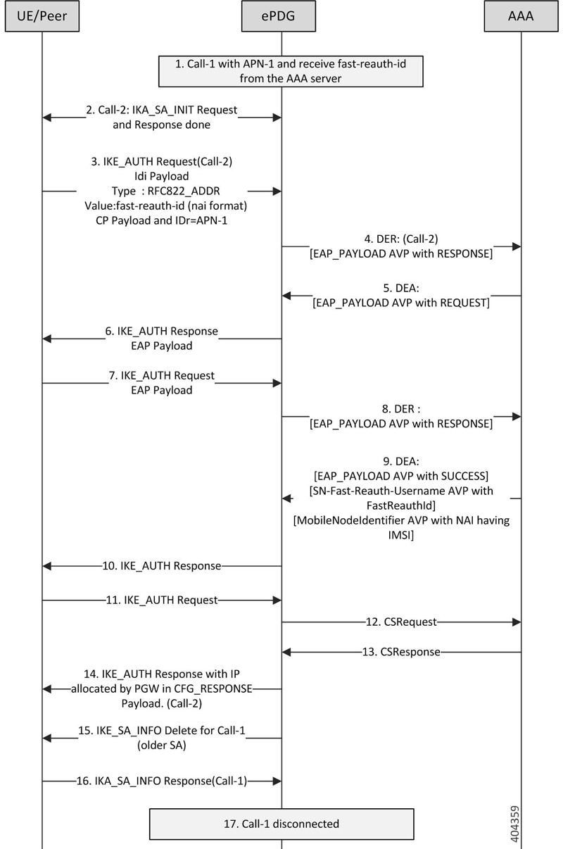
- Call-1 established for APN-1 and AAA-Server has provided fast-reauth-id during this authentication process. ePDG will store mapping between IMSI and fast-reauth-id.
- UE starts Call-2 for fast-reauthentication by sending the IKE-SA-INIT message to ePDG. IKE-SA established between UE and ePDG with IKA_SA_INIT message exchange.
- The UE sends the fast-reauth-id in NAI format(fast-reauth-idrealm) in the IDi payload and the APN-1 (in the IDr payload) in this first message of the IKE_AUTH phase, and begins negotiation of child security associations. The UE omits the AUTH parameter in order to indicate to the ePDG that it wants to use EAP over IKEv2. The UE includes the configuration payload (CFG_REQUEST) within the IKE_AUTH request message to give indication that it needs to reconfigure the IP address.
- ePDG Identifies the previous session based on the received fast-reauth-id as it already created mapping. ePDG will handle this request as new session. This is because the presence of CP-Payload indicates that the call should be established till PGW without retaining the IP address(S2B interface). The ePDG sends the Diameter-EAP-Request message to the 3GPP AAA Server, containing the fast-reauth-id and APN.Important:Please note that ePDG uses the new diameter-session-id here as it is creating a new session.
- The 3GPP AAA Server shall validate the fast-reauthentication-id and initiates the fast re-authentication request.Important:Please note that there is no communication with HSS/HLR at this stage since fast-reauthentication-id is used. This makes the procedure faster and reduce load in HSS.
- The ePDG responds with its identity, a certificate, and sends the AUTH parameter to protect the previous message it sent to the UE (in the IKE_SA_INIT exchange). The EAP message received from the 3GPP AAA Server (EAP-Request/Fast-Reauthentication) is included in order to start the EAP procedure over IKEv2.
- The UE checks the authentication parameters and responds to the fast-reauthentication. The only payload (apart from the header) in the IKEv2 message is the EAP message.
- The ePDG forwards the EAP-Response/Fast-Reauthentication message to the 3GPP AAA Server.
- The AAA checks, if the Fast-Reauthentication response is correct. When all checks are successful, the 3GPP AAA Server sends the final Diameter-EAP-Answer(with a result code indicating success) including the users IMSI, relevant service authorization information, an EAP success and the key material to the ePDG. This key material shall consist of the MSK generated during the fast-reauthentication process. AAA-Server shall include the SN-Fast-Reauth-Username AVP with the fast-reauthentication-id value given to UE in step 5. ePDG creates mapping between IMSI and Fast-reauthentication-ID at this point.
- The EAP Success message is forwarded to the UE over IKEv2.
- The UE shall take its own copy of the MSK as input to generate the AUTH parameter to authenticate the first IKE_SA_INIT message. The AUTH parameter is sent to the ePDG in IKE_AUTH message.
- The ePDG checks the correctness of the AUTH received from the UE. At this point the UE is authenticated. In S2b interface, ePDG initiates GTPv2 signaling between ePDG and PDN GW for creating the default-bearer for APN by sending Create-Session-Request to PGW with UE/APN details and request for IP-address allocation.
- PGW responds with the Create-Session-Response message containing the allocation IP address, QoS details for this default-bearer connection.
- The ePDG calculates the AUTH parameter which authenticates the second IKE_SA_INIT message. The ePDG sends the assigned Remote IP address in the configuration payload (CFG_REPLY) in the IKE_AUTH_RESPONSE message to UE. Fast-reauthentication is completed and Call-2 is connected now.
- ePDG initiates the IKE-SA INFO_DELETE message for Call-1 to UE to delete the IKE-SA as part of call deletion.
- UE responds with IKE-SA INFO_DELETE to delete the IKE-SA.
- Call-1 is disconnected at ePDG.
Figure 8. Multi-pdn with fast-reauth-id (fast-reauth-id Per UE case with CP Payload)
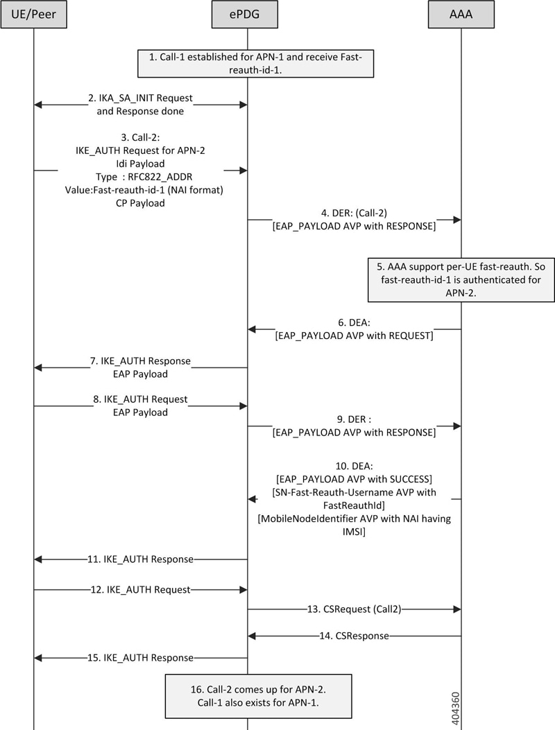
- Call-1 established for APN-1 and AAA-Server has provided fast-reauth-id-1 during this authentication process. ePDG will store mapping between imsi and fast-reauth-id-1
- UE starts Call-2 to connect to APN-2 using the fast-reauth-id-1. IKE-SA established between UE and ePDG with IKA_SA_INIT message exchange.
- The UE sends the fast-auth-id-1 in NAI format(fast-reauth-id-1realm) in the IDi payload and the APN-2 (in the IDr payload) in this first message of the IKE_AUTH phase, and begins negotiation of child security associations. The UE omits the AUTH parameter in order to indicate to the ePDG that it wants to use EAP over IKEv2. The UE includes the configuration payload (CFG_REQUEST) within the IKE_AUTH request message to give indication that it needs to configure the IP address.
- ePDG Identifies the previous session based on the received Fast-reauth-id as it already created mapping. ePDG will handle this request as new session. This is because the request is for new APN and also the presence of CP-Payload indicates that the call should be established till PGW without retaining the IP address(S2B interface). The ePDG sends the Diameter-EAP-Request message to the 3GPP AAA Server, containing the fast-reauth-id-1 and APN-2. Please note that ePDG uses the new diameter-session-id here as it is creating a new session.
- AAA server supports Fast-Reauthentication on per-UE basis. Hence it accepts fast-reauth-id-1 for APN-2.
- The 3GPP AAA Server validates the fast-reauth-id-1 and initiates the fast re-authentication request.Important:Please note that there is no communication with HSS/HLR at this stage since fast-reauth-id-1 is used. This makes the procedure faster and reduce load in HSS.The ePDG responds with its identity, a certificate, and sends the AUTH parameter to protect the previous message it sent to the UE (in the IKE_SA_INIT exchange). The EAP message received from the 3GPP AAA Server (EAP-Request/Fast-Reauthentication) is included in order to start the EAP procedure over IKEv2.
- The UE checks the authentication parameters and responds to the fast-reauthentication. The only payload (apart from the header) in the IKEv2 message is the EAP message.
- The ePDG forwards the EAP-Response/Fast-Reauthentication message to the 3GPP AAA Server.
- The AAA checks if the Fast-reauthentication response is correct. When all checks are successful, the 3GPP AAA Server sends the final Diameter-EAP-Answer(with a result code indicating success) including the users IMSI, relevant service authorization information, an EAP success and the key material to the ePDG. This key material consists of the MSK generated during the fast-reauthentication process. AAA-Server includes the SN-Fast-Reauth-Username AVP with the fast-reauthentication-id value given to UE in step 5. ePDG creates mapping between IMSI and Fast-reauthentication-ID at this point.
- The EAP Success message is forwarded to the UE over IKEv2.
- The UE shall take its own copy of the MSK as input to generate the AUTH parameter to authenticate the first IKE_SA_INIT message. The AUTH parameter is sent to the ePDG in IKE_AUTH message.
- The ePDG checks the correctness of the AUTH received from the UE. At this point the UE is authenticated. In S2b interface, ePDG initiates GTPv2 signaling between ePDG and PDN GW for creating the default-bearer for APN by sending Create-Session-Request to PGW with UE/APN details and request for IP-address allocation.
- PGW responds with the Create-Session-Response message containing the allocation IP address, QoS details for this default-bearer connection.
- The ePDG calculates the AUTH parameter which authenticates the second IKE_SA_INIT message. The ePDG shall send the assigned Remote IP address in the configuration payload (CFG_REPLY) in the IKE_AUTH_RESPONSE message to UE.
- Call-2 is connected now for APN-2 and Call-1 already exists for APN-1.
ePDG Offline charging
ePDG Offline charging Architecture
Offline charging is a process where charging information is collected concurrently with that resource usage. The charging information is then passed through a chain of logical charging functions. At the end of this process, CDR files are generated by the network, which are then transferred to the network operator’s Billing Domain(BD). Charging information like amount of data transmitted in uplink and downlink direction are collected as part of ePDG-CDR are used to inter-operator settlements.The ePDG Offline charging involves the following functionalists for WLAN 3GPP IP Access:
- Charging Trigger Function
- Charging Data Function
- Ga Reference Point
Figure 9. ePDG Offline Charging Architecture
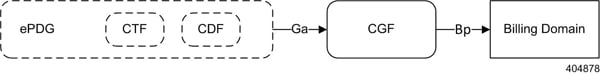
The Charging Trigger Function (CTF) which is an integrated component generates charging events and forwards them to the Charging Data Function (CDF). The CDF, in turn generates ePDG-CDRs which are then transferred to the CGF. Finally, the CGF create ePDG-CDR files and forwards them to the Billing Domain. The CTF and CDF are integrated in ePDG, however, the CGF may exist as a physically separate entity or integrated to ePDG. If the CGF is external to the ePDG, then the CDF forwards the CDRs to the CGF across the Ga interface (using GTPP protocol defined in TS 32.295). ePDG-CDR format is as defined in TS 32.298 v12.6.0.Figure 10. ePDG Offline Charging Callflow
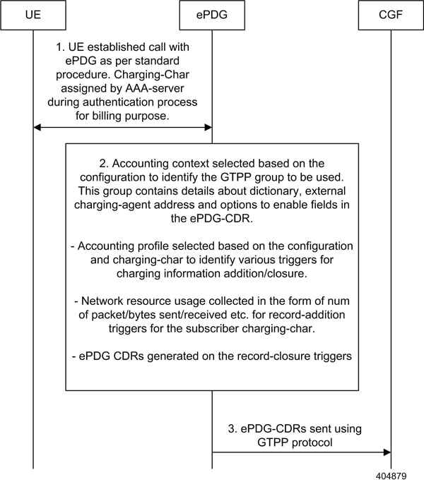
ePDG Offline Charging
ePDG supports CDRs to bill the UEs for network resource usage as defined in 3GPP specification TS32.298.Apart from the standard ePDG-CDR fields ePDG Offline Charging feature populates the following additional fields:
- IKEv2 tunnel endpoint IP address(UE Side tunnel endpoint address)
- Source Port number used in IKEv2 tunnel
- ePDG SWu interface IP address(ePDG side tunnel endpoint address)
- Destination Port number used in IKEv2 tunnel
- AP-MAC address used by UE to connect in WLAN network
Custom24 is the GTPP dictonary for standard ePDG-CDR as per specfications and custom38 is the GTPP dictionary for CDRs with above additional fields.
Supported Triggers for ePDG-CDRs Charging Information Addition
The „List of Traffic Volumes“ attribute of the ePDG-CDR consists of a set of containers, on encountering the following trigger conditions, the charging information will be added to the container:
Qos Change: A change in the QoS will result to open the „List of Traffic Data Volumes“ container being closed and added to the CDR and a new bearer specific container is opened. Also when there is a Change in QoS, the trigger will be sent to accounting module for CDR information addition using the API „sessmgr_acct_api_event(handle, params)“ with the params —> qos_change set from the sessmgr.
Tariff time: On reaching the Tariff Time Change open „List of Traffic Data Volumes“ containers is closed and added to the CDR. Tariff-time change is to add charging information to CDR during a particular tariff-time of day.
Record Closure: Open „List of Traffic Data Volumes“ containers is closed and added to the ePDG-CDR.
Supported Triggers for ePDG-CDR closure
The following events trigger closure and sending of ePDG-CDR:
Time Limit: CDRs are generated after every x seconds where x is the configured time limit.
Max container Triggers: Maximum number of charging condition changes (QoS/tariff time change). CDRs are generated when the max bucket limit is reached. By default its 4.
Volume limit trigger: CDRs are generated whenever the uplink or downlink data volume for the session crosses the configured uplink, downlink or total limit.
Management Intervention: CDRs can be generated by management intervention such as clear command issued by the operator to cleanup a session.
Assumptions and Limitations
- The AP-MAC address will be populated in ePDG-CDR only when it is supplied by UE during initial IKEv2 exchange in IDi payload as expected by ePDG. Please see the ePDG admin guide to understand the format of IDi payload with AP-MAC address encoded in it.
- The CDF functionality is integrated within ePDG. RF interface is not support.
UE Local IP Address IE in the S2B Interface over GTPv2
This chapter describes UE Local IP Address IE in the S2B Interface over GTPv2 feature, below are the links to main sections of the document:
The location of the UE initiating a VoWifi call via ePDG will be identified based on the UE local IP address reported on s2b interface. This location information can be used for multiple purposes like billing and lawful interception etc.
Below is the specifications of the „UE Local IP Address IE in the S2B Interface over GTPv2“ feature:
- ePDG saves the UE local IP address (SRC address of the IKE messages received from UE) and the port (SRC port of the IKE message received from UE) and send them to PGW over S2B interface.
- The port information must be sent on S2B interface only when a NAT is detected between UE and ePDG (UE is behind a NAT).
- CLI configuration is supported to control the inclusion of the UE local IP Address and port on the S2B interface.
- The above functionality needs to be supported only for GTPv2 based S2B interface.
How It Works
This section describes signaling flow during an ePDG session setup procedure.Figure 11. ePDG Session Setup Procedure
The above figure shows the signaling flow during an ePDG session setup procedure:
- The IKEv2 procedure starts with the IKE_INIT (step 2) message received at ePDG from UE. The SRC address and port of the IKE_INIT message is recorded at ePDG and NAT detection is done as defined in RFC 5996.
- The IKE_INIT message triggers the IKEv2 tunnel setup and after the IKE_INIT_RESP in step 3, the UE sends IKE_AUTH message (step 4).
- This IKE_AUTH_REQ from UE triggers the multi round authentication with AAA server on SWm interface.
- ePDG sends IKE_AUTH_RESP in step 11 to complete the EAP authentication.
- The next IKE_AUTH_REQ from UE triggers the session setup towards the PGW over s2b interface and ePDG should include the „UE Local IP Address“ and „UE UDP Port“ (only if NAT detected) AVPs in the Create Session Request message.
Important:
UE Local IP Address IE in the S2B Interface over GTPv2″ supports only for GTPv2 based s2b interface.
Detailed Description
Following table summarizes the expected behavior for UE Local IP Address IE in the S2B Interface over GTPv2 feature.
| SR.No | AVP Inclusion via configuration | NAT detected on SWu Interface | Expected Behavior |
|---|---|---|---|
| 1. | Enabled | Yes | Both „UE Local IP Address“ and „UE UDP Port“ AVPs are sent in Create Session Request message to PGW. |
| 2. | Enabled | No | Only „UE Local IP Address“ AVP is sent in Create Session Request message to PGW. |
| 3. | Disabled | Yes | Both „UE Local IP Address“ and „UE UDP Port“ AVPs are NOT sent in Create Session Request message to PGW. |
| 4. | Disabled | No | Both „UE Local IP Address“ and „UE UDP Port“ AVPs are NOT sent in Create Session Request message to PGW. |
External Interfaces
This feature impacts the GTPv2 based s2b interface towards PGW. The following two AVPs as defined in 3GPP 29.274 are included in the Create Session Requested message as per the conditions mentioned in the above table.
| Attribute | Condition | Description | Content |
|---|---|---|---|
| UE Local IP Address | CO | The ePDG should include this IE on S2b interface based on local policy for Fixed Broadband access network interworking see 3GPP in TS 23.139 [51]. | IP Address |
| UE UDP Port | CO | The ePDG shall include this IE on S2b interface if NAT is detected and UE Local IP Address is present for Fixed Broadband access network interworking see 3GPP in TS 23.139 [51]. | Port Number |
Note: Even though the 3GPP specification mentions the usage of the AVPs in the context of Fixed Broadband access network, they are being used for untrusted WiFi access in this case.
Lawful Intercept
The IKEv2 Fragmentation feature enables IPSec to fragment large messages at IKEv2 and replace them with a series of smaller messages as defined in RFC 7383. This ensures that fragmentation does not occur at IP level and fragmented packets are not dropped.
For more information on this feature, refer the IKEv2 Fragmentation chapter in the IPSec Reference guide.
IKEv2 Fragmentation Support
The IKEv2 Fragmentation feature enables IPSec to fragment large messages at IKEv2 and replace them with a series of smaller messages as defined in RFC 7383. This ensures that fragmentation does not occur at IP level and fragmented packets are not dropped.
For more information on this feature, refer the IKEv2 Fragmentation chapter in the IPSec Reference guide.
How the ePDG Works
This section describes the ePDG during session establishment and disconnection.
- ePDG Session Establishment
- UE-initiated Session Disconnection
- ePDG-initiated Session Disconnection
- P-GW-initiated Session Disconnection
- WiFi-to-WiFi Re-Attach With Same ePDG
- WiFi to LTE Handoff with Dedicated Bearer (UE initiated)
- LTE to WiFi Hand Off – With Dedicated bearer (UE initiated)
ePDG Session Establishment
The figure below shows an ePDG session establishment flow. The table that follows the figure describes each step in the flow.Figure 12. ePDG Session Establishment
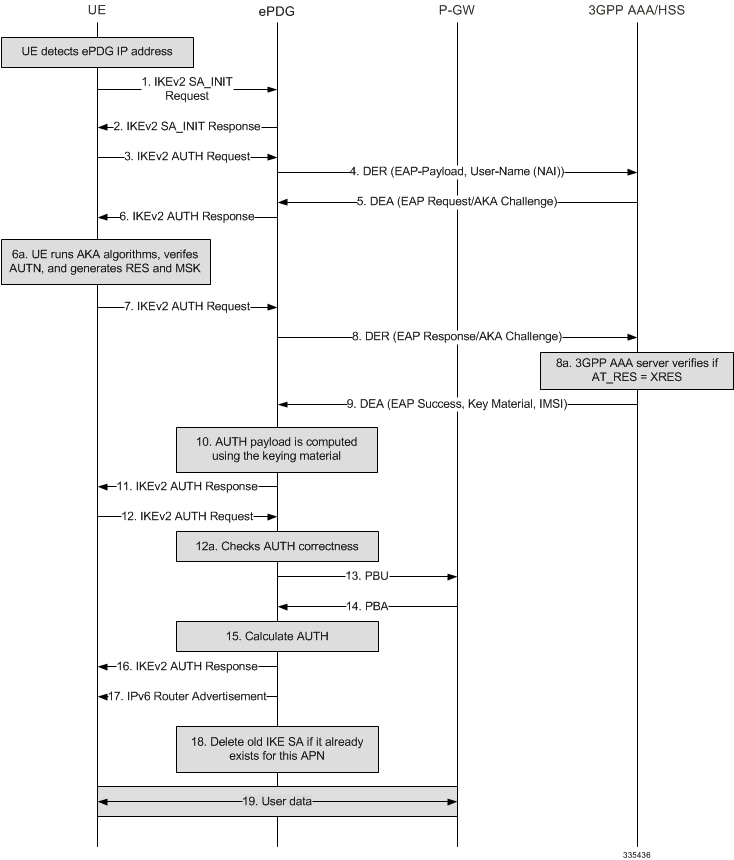
| Step | Description |
|---|---|
| 1. | The WLAN UE initiates an IKEv2 exchange with the ePDG by issuing an IKEv2 SA_INIT Request message to negotiate cryptographic algorithms, exchange nonces, and perform a Diffie-Hellman exchange with the ePDG. |
| 2. | The ePDG returns an IKEv2 SA_INIT Response message. |
| 3. | The UE sends the user identity in the IDi payload and the APN information in the IDr payload in the first message of the IKE_AUTH phase and begins negotiation of Child SAs. The UE omits the AUTH parameter in order to indicate to the ePDG that it wants to use EAP over IKEv2. The user identity is compliant with the NAI (Network Access Identifier) format specified in TS 23.003 and contains the IMSI as defined for EAP-AKA in RFC 4187. The UE sends the CP payload (CFG_REQUEST) within the IKE_AUTH Request message to obtain an IPv4 and/or IPv6 home IP address and/or a home agent address. The root NAI is in the format „0<IMSI>nai.epc.mnc<MNC>.mcc<MCC>.3gppnetwork.org“. |
| 4. | The ePDG sends a DER (Diameter EAP Request) message containing the user identity and APN to the 3GPP AAA server. |
| 5. | The 3GPP AAA server fetches the user profile and authentication vectors from the HSS/HLR if these parameters are not available on the 3GPP AAA server. The 3GPP AAA server looks up the IMSI of the authenticated user based on the received user identity (root NAI) and includes EAP-AKA as the requested authentication method in the request sent to the HSS. The HSS generates the authentication vectors with the AMF separation bit = 0 and sends them back to the 3GPP AAA server. The 3GPP AAA server checks the user’s subscription information to verify that the user is authorized for non-3GPP access. The 3GPP AAA server increments the counter for IKEv2 SAs. If the maximum number of IKE SAs for the associated APN is exceeded, the 3GPP AAA server sends an indication to the ePDG that established the oldest active IKEv2 SA (it could be the same ePDG or a different one) to delete the oldest IKEv2 SA. The 3GPP AAA server updates its total active IKEv2 SAs for the APN.The 3GPP AAA server initiates the authentication challenge and responds with a DEA (Diameter EAP Answer). The user identity is not requested again. |
| 6. | The ePDG responds with its identity (a certificate) and sends the AUTH parameter to protect the previous message it sent to the UE in the IKEv2 SA_INIT exchange. It completes the negotiation of the Child SAs, if any. The EAP Request/AKA Challenge message received from the 3GPP AAA server is included in order to start the EAP procedure over IKEv2. |
| 6a. | The UE checks the authentication parameters. |
| 7. | The UE responds to the authentication challenge with an IKEv2 AUTH Request message. The only payload apart from the header in the IKEv2 message is the EAP Response/AKA Challenge message. |
| 8. | The ePDG forwards the EAP Response/AKA Challenge message to the 3GPP AAA server in a DER message. |
| 8a. | The 3GPP AAA server checks if the authentication response is correct. |
| 9. | When all checks are successful, the 3GPP AAA server sends the final DEA (with a result code indicating EAP success) that includes the relevant service authorization information and key material to the ePDG. The key material consists of the MSK generated during the authentication process. The MSK is encapsulated in the EAP-Master-Session-Key-AVP as defined in RFC 4072. |
| 10. | The MSK is used by the ePDG to generate the AUTH parameters in order to authenticate the IKEv2 SA_INIT messages as specified for IKEv2 in RFC 4306. These first two messages had not been authenticated earlier as there was no key material available yet. Per RFC 4304, the shared secret generated in an EAP exchange (the MSK) when used over IKEv2 must be used to generate the AUTH parameters. |
| 11. | The EAP Success/Failure message is forwarded to the UE over IKEv2. |
| 12. | The UE takes its own copy of the MSK as input to generate the AUTH parameter to authenticate the first IKEv2 SA_INIT message. The AUTH parameter is sent to the ePDG. |
| 12a. | The ePDG checks the correctness of the AUTH parameter received from the UE. At this point the UE is authenticated. |
| 13. | On successful authentication, the ePDG establishes the PMIP tunnel towards the P-GW by sending a PBU (Proxy-MIP Binding Update), which includes the NAI and APN and the Home Network Prefix or IPv4 Home Address option. |
| 14. | The P-GW allocates the requested IP address (IPv4/IPv6 or both) session and responds back to the ePDG with a PBA (Proxy-MIP Binding Acknowledgement). |
| 15. | The ePDG calculates the AUTH parameter that authenticates the second IKEv2 SA_INIT message. |
| 16. | The ePDG sends the AUTH parameter, the assigned remote IP address in the CP payload, the SAs, and the rest of the IKEv2 parameters to the UE, and IKEv2 negotiation is complete. |
| 17. | The ePDG sends an IPv6 Router Advertisement to the UE to ensure that the IPv6 stack is fully initialized. |
| 18. | If the ePDG detects that an old IKEv2 SA for the APN already exists, it deletes the IKEv2 SA and sends an INFORMATIONAL exchange with a DELETE payload to the UE to delete the old IKEv2 SA in the UE as specified in RFC 4306. |
| 19. | The ePDG session/IPSec SA is fully established and ready for data transfer. |
UE-initiated Session Disconnection
The figure below shows the message flow during a UE-initiated session disconnection. The table that follows the figure describes each step in the message flow.Figure 13. UE-initiated Session Disconnection
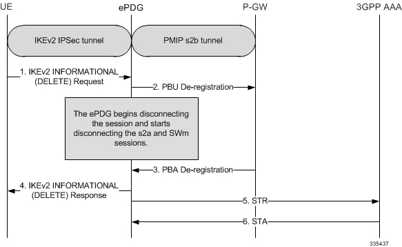
| Step | Description |
|---|---|
| 1. | The UE sends an INFORMATIONAL Request. The Encrypted Payload has a single Delete Payload which contains the SPI of the IKEv2 SA corresponding to the WLAN UE session to be disconnected. |
| 2. | On receiving the IKEv2 INFORMATIONAL Request with Delete from the UE, the ePDG begins the disconnection of the WLAN UE session. It begins the tear down the session by sending PBU for deregistration to P-GW to disconnect the session. |
| 3. | P-GW sends back the PBA message acknowledging the session deletion. |
| 4. | The ePDG responds back to the UE’s IKEv2 INORMATION request with a IKEv2 INFORMATIONAL RSP. |
| 6. | 3GPP AAA clears the SWn sessions and responds back to the ePDG with a Session-Terminate-Ack (STA). |
Figure 14. UE initiated Session Disconnection – GTPv2
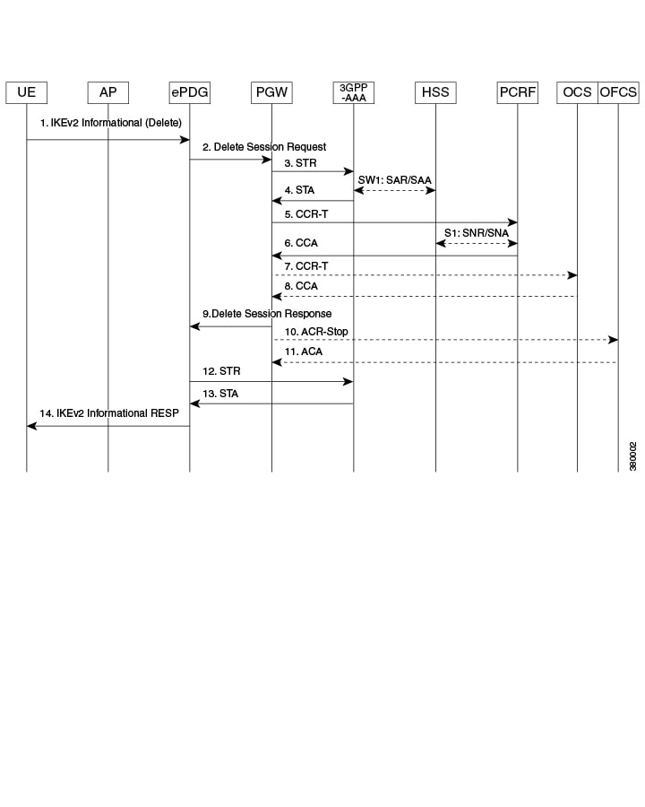
| Step | Description |
|---|---|
| 1. | The UE sends an INFORMATIONAL Request. The Encrypted Payload has a single Delete Payload which contains the SPI of the IKEv2 SA corresponding to the WLAN UE session to be disconnected. |
| 2. | On receiving the IKEv2 INFORMATIONAL Request with Delete from the UE, the ePDG begins the disconnection of the WLAN UE session. It begins the tear down the session by sending Delete quest (Linked Bearer ID) to P-GW to disconnect the session. |
| 3. | P-GW sends back the Delete Session Response message acknowledging the session deletion. |
| 4. | ePDG disconnects the SWm session with sending a Session-Terminate-Request (STR) to the 3GPP AAA. |
| 5. | 3GPP AAA clears the SWn sessions and responds back to the ePDG with a Session-Terminate-Ack (STA). |
| 6. | The ePDG responds back to the UE’s IKEv2 INORMATION request with a IKEv2 INFORMATIONAL RSP. |
ePDG-initiated Session Disconnection
The figure below shows the message flow during an ePDG-initiated session disconnection. The table that follows the figure describes each step in the message flow.Figure 15. ePDG-initiated Session Disconnection
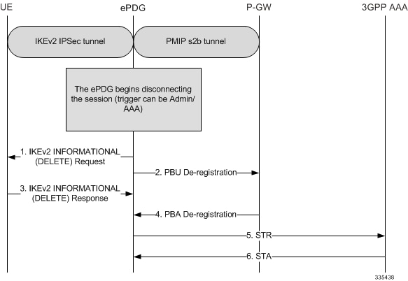
| Step | Description |
|---|---|
| 1. | An Admin/AAA trigger causes the ePDG to start disconnecting the WLAN UE session by sending an IKEv2 INFORMATIONAL (DELETE) Request message. The encrypted payload has a single DELETE payload that contains the SPI of the IKEv2 SA corresponding to the WLAN UE session being disconnected. |
| 2. | The ePDG also begins to tear down the S2b PMIP session by sending a PBU (Proxy-MIP Binding Update) De-registration message to the P-GW.Note In case the protocol used on S2b is GTPv2 then the „Delete Session Request“ message shall be used instead of PBU. |
| 3. | The ePDG responds to the UE’s IKEv2 INFORMATIONAL (DELETE) Request message with an IKEv2 INFORMATIONAL (DELETE) Response message. |
| 4. | On receiving the PBU (Proxy-MIP Binding Update) De-registration message, the P-GW disconnects the UE session and releases local resources. The P-GW completes the disconnection of the WLAN UE session and responds to the ePDG with a PBA De-registration message.Note In case the protocol used on S2b is GTPv2 then the „Delete Session Response“ message shall be used instead of PBA. |
| 5. | The ePDG disconnects the SWu session by sending an STR (Session Terminate Request) message to the 3GPP AAA/HSS. |
| 6. | The 3GPP AAA clears the SWu sessions and responds to the ePDG with an STA (Session Terminate Acknowledgment) message. |
P-GW-initiated Session Disconnection
The figure below shows the message flow during a P-GW-initiated session disconnection. The table that follows the figure describes each step in the message flow.Figure 16. P-GW-initiated Session Disconnection
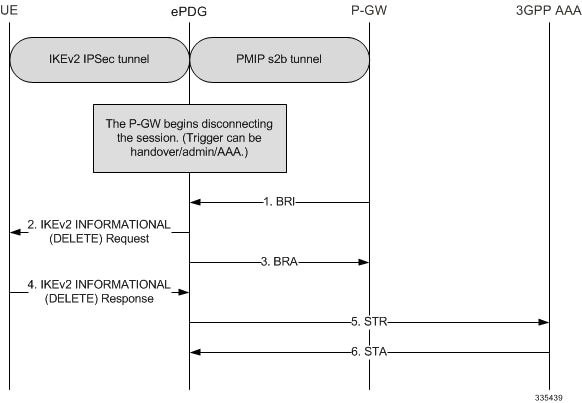
| Step | Description |
|---|---|
| 1. | The PGW sends BRI (Binding revocation indication) to ePDG for disconnecting the session. |
| 2. | The ePDG sends IKEv2 Informational Delete Request () to UE to disconnect the session. |
| 3. | The ePDG sends BRA (Binding revocation acknowledgement) to PGW acknowledging the session disconnect |
| 4. | The UE sends IKEv2 Informational Delete Response (). |
| 5. | ePDG sends STR (Session ID, Base AVPs, Termination Cause) to the 3GPP AAA. |
| 6. | 3GPP AAA clears the SWn sessions and responds back to the ePDG with a STA (Session ID, Base AVPs). |
WiFi-to-WiFi Re-Attach With Same ePDG
The figure below shows the message flow If the UE looses connection to the ePDG and then reconnects using the same ePDG. The table that follows the figure describes each step in the message flow.Figure 17. WiFi-to-WiFi Re-Attach
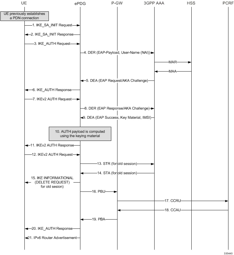
| Step | Description |
|---|---|
| 1. | The UE is authenticated and a PDN connection is established. This scenario addresses a case where the UE has ungracefully disconnected from the network and is reattaching to the network again. |
| 2. | The session is still active in the ePDG and P-GW along with AAA, PCRF and AAA. |
| 3. | The step 2 through 12 are identical to the UE initial attach scenario defined in section 3.2.1. It is assumed that the UE will not populate the IP Addresses in the IKE Config Request. |
| 4. | The ePDG shall be detecting the duplicate session and clearing the previous established session at its ends. Further ePDG shall be establishing new session on P-GW following below steps |
| 15. | ePDG UE: IKE_AUTH – The ePDG sends IKE_AUTH (AUTH, CP, SA, CFG_REPLY ([INTERNAL_IP4_ADDRESS], [INTERNAL_IP4_NETMASK], [INTERNAL_IP4_DNS], INTERNAL_IP6_ADDRESS, INTERNAL_IP6_SUBNET, INTERNAL_IP6_DNS, P-CSCF) TSi, TSr). The ePDG calculates the AUTH parameter, which authenticates the second IKE_SA_INIT message. The ePDG sends the assigned IP address in the configuration payload (CFG_REPLY). The AUTH parameter is sent to the UE together with the configuration payload, security associations and the rest of the IKEv2 parameters and the IKEv2 negotiation terminates. |
| 16. | ePDG P-GW: PBU (Proxy-MIP Binding Update) – The ePDG selects the P-GW based on DNS response from the APN-FQDN.The ePDG sends PBU (IMSI, [MSIDSN], Serving Network, RAT Type (WLAN), Indication Flags, Sender F-TEID for C-plane, APN, Selection Mode, PAA, APN-AMBR, Bearer Contexts), [Recovery], [Charging Characteristics], Private IE (P-CSCF). The F-TEID shall be set to zero so that P-GW shall handle the same as create-on-create case. |
| 19. | P-GW ePDG: PBA (Proxy-MIP Binding Acknowledgement) – The P-GW terminates the previous session by handling it as create on create case and establishes a new session. The P-GW allocates the requested IP address session and responds back to the ePDG with a PBA (Cause, P-GW S2b Address C-plane, PAA, [Recovery], APN-AMBR, Additional Protocol Configuration Option (APCO) Bearer Contexts Created, Private IE (P-CSCF)) message. |
| 21. | ePGD UE: Router Advertisement – The ePDG sends Router Advertisement to ensure IP Stack is fully initialized. |
Figure 18. WiFi-to-WiFi Re-Attach – GTPv2
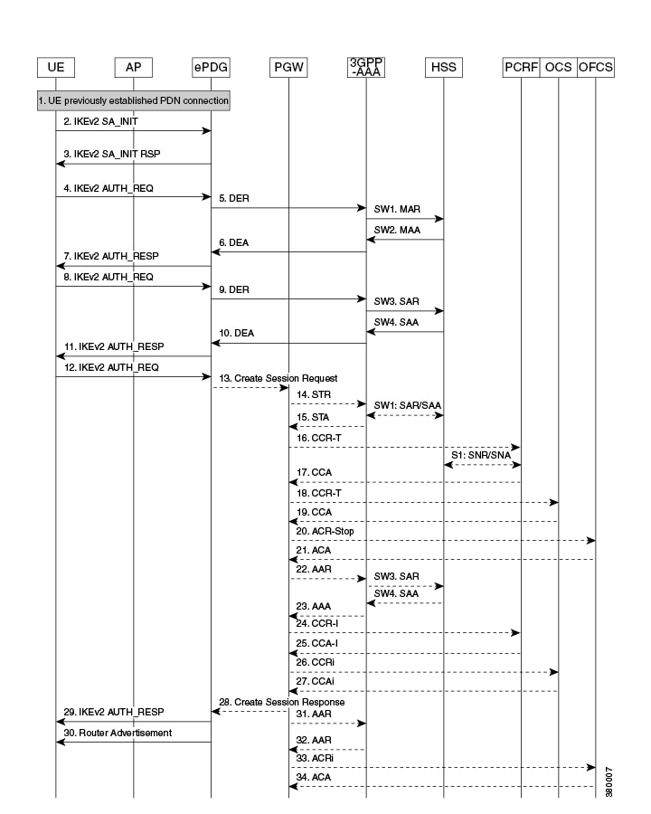
Description:
The UE is authenticated and a PDN connection is established. This scenario addresses a case where the UE has ungracefully disconnected from the network and is reattaching to the network again.
The session is still active in the ePDG and P-GW along with AAA, PCRF and AAA.
The step 2 through 12 are identical to the UE initial attach scenario defined in section 3.2.1. It is assumed that the UE will not populate the IP Addresses in the IKE Config Request.
The ePDG detects the duplicate session and clears the previous established session at its ends. Then the ePDG establishes a new session on the P-GW using the following steps:
| Step | Description |
|---|---|
| 13. | ePDG -> P-GW: Create Session Request – The ePDG selects the P-GW based on DNS response from the APN-FQDN.The ePDG sends Create Session Request (IMSI, [MSIDSN], Serving Network, RAT Type (WLAN), Indication Flags, Sender F-TEID for C-plane, APN, Selection Mode, PAA, APN-AMBR, Bearer Contexts), [Recovery], [Charging Characteristics], Private IE (P-CSCF). The TEID shall be set to zero so that P-GW shall handle the same as create-on-create case. |
| 14. | P-GW -> ePDG: Create Session Response – The P-GW terminates the previous session by handling it as create on create case and establishes a new session. The P-GW allocates the requested IP address session and responds back to the ePDG with a Create Session Response (Cause, P-GW S2b Address C-plane, PAA, [Recovery], APN-AMBR, Additional Protocol Configuration Option (APCO) Bearer Contexts Created, Private IE (P-CSCF)) message. |
| 29. | ePDG -> UE: IKE_AUTH – The ePDG sends IKE_AUTH (AUTH, CP, SA, CFG_REPLY ([INTERNAL_IP4_ADDRESS], [INTERNAL_IP4_NETMASK], [INTERNAL_IP4_DNS], INTERNAL_IP6_ADDRESS, INTERNAL_IP6_SUBNET, INTERNAL_IP6_DNS, P-CSCF) TSi, TSr).The ePDG calculates the AUTH parameter, which authenticates the second IKE_SA_INIT message. The ePDG sends the assigned IP address in the configuration payload (CFG_REPLY). The AUTH parameter is sent to the UE together with the configuration payload, security associations and the rest of the IKEv2 parameters and the IKEv2 negotiation terminates. |
| 30. | ePDG -> UE: Router Advertisement – ePDG sends Router Advertisement to ensure IP Stack is fully initialized. |
WiFi to LTE Handoff with Dedicated Bearer (UE initiated)
When a VoLTE call is ongoing, the P-GW will install the bearers on the LTE network using piggyback procedure.Figure 19. WiFi to LTE Handoff with Dedicated Bearer – Part 1
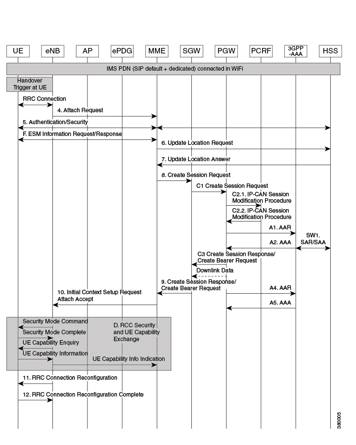
Figure 20. WiFi to LTE Handoff with Dedicated Bearer – Part 2
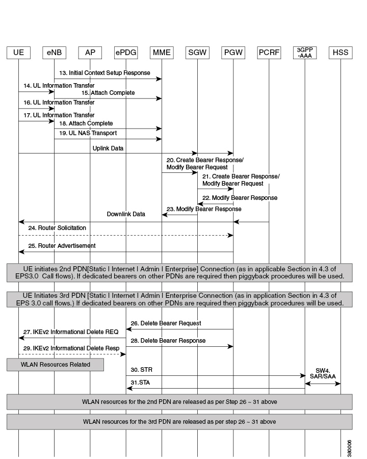
| Note | This call flow is the similar as that for IMSI/GUTI-based EUTRAN Attach, except for the additional steps for session clean up on WiFi network and multiple dedicated bearers are set up if voice and video media bearers are present. The critical difference is that the Handover Indication bit shall be set in Create Session Request message. |
The UE which was previously having a WiFi call attaches to the LTE.
| Step | Description |
|---|---|
| 26. | P-GW -> ePDG: Delete Bearer Request – The P-GW sends Delete Bearer Request (EPS Bearer ID / LBI, Cause) to ePDG to disconnect the session.If releasing all the bearers LBI shall be set to the identity of the default bearer associated with the PDN connection.Cause shall be set to „Access changed from Non-3GPP to 3GPP“. |
| 27. | ePDG -> UE: IKEv2 Information Delete Request – The ePDG sends IKEv2 Informational Delete Request () to UE to disconnect the session. |
| 28. | ePDG -> P-GW: Delete Bearer Response – The ePDG sends Delete Bearer Response (Cause, Linked EPS Bearer Identity, Bearer Context, [Recovery]) to P-GW. |
| 29. | UE -> ePDG: IKEv2 Informational Delete Response – UE responds with IKEv2 Information Delete Response () and initiates air interface resource releaseStep is conditional and UE may not send this response. |
| 30. | ePDG -> AAA: Session Termination Request – The ePDG sends STR (Session ID, User-Name (IMSI-NAI), Termination-Cause) to the 3GPP AAA. |
| 31. | AAA -> ePDG: Session Termination Answer – The AAA sends STA (Session ID, Result-Code) to the ePDG. |
LTE to WiFi Hand Off – With Dedicated bearer (UE initiated)
In this call flow we use the IMS PDN with an ongoing VoLTE call with the associated dedicated bearers.
The UE detects suitable WiFi access point and connects to AP as per node selection.Figure 21. LTE to WiFi Hand Off – With Dedicated Bearer
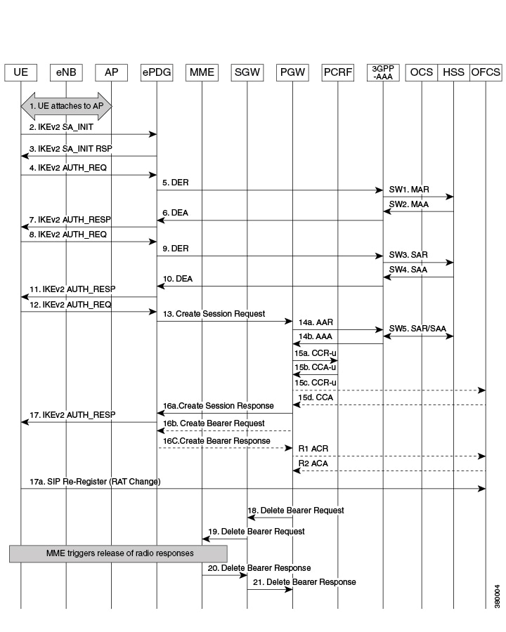
| Step | Description |
|---|---|
| 2. | UE -> ePDG: The UE sends IKE_SA_INIT Message. |
| 3. | ePDG -> UE: The ePDG responds with IKE_SA_INIT_RSP Message. |
| 4. | The UE sends the user identity (in the IDi payload) and the APN information (in the IDr payload) in this first message of the IKE_AUTH phase, and begins negotiation of child security associations. The UE omits the AUTH parameter in order to indicate to the ePDG that it wants to use EAP over IKEv2. The user identity shall be compliant with Network Access Identifier (NAI) format specified in TS 23.003 containing the IMSI, as defined for EAP-AKA in RFC 4187. The UE shall send the configuration payload (CFG_REQUEST) within the IKE_AUTH request message with the preserved IP address(es) from the LTE session so that ePDG knows its handoff case and communicates same IP address to P-GW. When the MAC ULI feature is enabled the root NAI used will be of the form „0<IMSI>AP_MAC_ADDR:nai.epc.mnc<MNC>.mcc<MCC>.3gppnetwork.org“. |
| 5. | The ePDG sends the Authentication and Authorization Request message to the 3GPP AAA Server, containing the user identity and APN. |
| 6. | The 3GPP AAA Server shall fetch the user profile and authentication vectors from HSS/HLR (if these parameters are not available in the 3GPP AAA Server). The 3GPP AAA Server shall lookup the IMSI of the authenticated user based on the received user identity (root NAI) and include the EAP-AKA as requested authentication method in the request sent to the HSS. The HSS shall then generate authentication vectors with AMF separation bit = 0 and send them back to the 3GPP AAA server. The 3GPP AAA Server checks in user’s subscription if he/she is authorized for non-3GPP access. The counter of IKE SAs for that APN is stepped up. If the maximum number of IKE SAs for that APN is exceeded, the 3GPP AAA Server shall send an indication to the ePDG that established the oldest active IKE SA (it could be the same ePDG or a different one) to delete the oldest established IKE SA. The 3GPP AAA Server shall update accordingly the information of IKE SAs active for the APN.The 3GPP AAA Server initiates the authentication challenge. The user identity is not requested again. |
| 7. | The ePDG responds with its identity, a certificate, and sends the AUTH parameter to protect the previous message it sent to the UE (in the IKE_SA_INIT exchange). It completes the negotiation of the child security associations if any. The EAP message received from the 3GPP AAA Server (EAP-Request/AKA-Challenge) is included in order to start the EAP procedure over IKEv2. |
| 8. | The UE checks the authentication parameters and responds to the authentication challenge. The only payload (apart from the header) in the IKEv2 message is the EAP message. |
| 9. | The ePDG forwards the EAP-Response/AKA-Challenge message to the 3GPP AAA Server. |
| 9a. | The AAA checks, if the authentication response is correct. |
| 9b. | When all checks are successful, the 3GPP AAA Server sends the final Authentication and Authorization Answer (with a result code indicating success) including the relevant service authorization information, an EAP success and the key material to the ePDG. This key material shall consist of the MSK generated during the authentication process. When the SWm and SWd interfaces between ePDG and 3GPP AAA Server are implemented using Diameter, the MSK shall be encapsulated in the EAP-Master-Session-Key-AVP, as defined in RFC 4072. |
| 10. | The MSK shall be used by the ePDG to generate the AUTH parameters in order to authenticate the IKE_SA_INIT phase messages, as specified for IKEv2 in RFC 4306. These two first messages had not been authenticated before as there was no key material available yet. According to RFC 4306 [3], the shared secret generated in an EAP exchange (the MSK), when used over IKEv2, shall be used to generated the AUTH parameters. |
| 11. | The EAP Success/Failure message is forwarded to the UE over IKEv2. |
| 12. | UE -> ePDG: IKEv2 AUTH_REQUEST – The UE sends Auth_Request (IDi, [CERT] | [CERTREQ], IDr (CP), SA (CFQ_REQUEST (INTERNAL_IP4_ADDRESS, INTERNAL_IP4_NETMASK INTERNAL_IP6_ADDRESS, INTERNAL_IP6_SUBNET, INTERNAL_IP4_DNS, INTERNAL_IP6_DNS, TSi, TSr, P-CSCF)Note The INTERNAL_IP4_ADDRESS and/or INTERNAL_IP6_ADDRESS must be populated with the IP addresses previously assigned on LTE to indicate that this is a handover. |
| 13. | ePDG -> P-GW: Create SessKPIsion Request – The ePDG sends Create Session Request (IMSI, Serving Network, RAT Type (WLAN), Indication Flags (handover=1, DAB=IPv4v6), Sender F-TEID for C-plane, APN, Selection Mode, PAA, APN-AMBR, Bearer Contexts) to the P-GW.Selection Mode shall be set to „MS or network provided APN, subscribed verified“. |
| 16a. | P-GW -> ePDG: Create Session Response – The P-GW allocates the requested IP address session and responds back to the ePDG with a Create Session Response (Cause, P-GW S2b Address C-plane, PAA, Bearer Contexts Created, APN-AMBR, Recovery, Additional Protocol Configuration Options (APCO). Private Extension) message |
| 16b. | P-GW -> ePDG: Create Bearer Request – If there are PCC rules that require a dedicated bearer, the P-GW sends Create Bearer Request (LBI, Bearer Contexts (EPS Bearer ID, TFT, S2b-U PGW F-TEID, Bearer Level QoS)) to the ePDG. Note that Charging ID is not sent on S2b. |
| 16c. | The ePDG sends Create Bearer Response (Cause, Bearer Context (EPS Bearer ID, Cause, S2b-U ePDG F-TEID, S2b-U PGW F-TEID), [Recovery]) message. |
| 17. | ePDG -> UE: IKE_AUTH – The ePDG calculates the AUTH parameter, which authenticates the second IKE_SA_INIT message. The ePDG sends the assigned IP address in the configuration payload (CFG_REPLY). The AUTH parameter is sent to the UE together with the configuration payload, security associations and the rest of the IKEv2 parameters and the IKEv2 negotiation terminates. |
Supported Standards
The ePDG service complies with the following standards:
3GPP References
- 3GPP TS 23.234-b.0.0: „3rd Generation Partnership Project; Technical Specification Group Services and System Aspects; 3GPP system to Wireless Local Area Network (WLAN) interworking; System description (Release 11)“.
- 3GPP TS 24.301-b.7.0: „3rd Generation Partnership Project; Technical Specification Group Core Network and Terminals; Non-Access-Stratum (NAS) protocol for Evolved Packet System (EPS)“.
- 3GPP TS 23.402-b.7.0: „3rd Generation Partnership Project; Technical Specification Group Services and System Aspects; Architecture enhancements for non-3GPP accesses (Release 9)“.
- 3GPP TS 24.302-b.7.0: „3rd Generation Partnership Project; Technical Specification Group Core Network and Terminals; Access to the 3GPP Evolved Packet Core (EPC) via non-3GPP access networks; Stage 3 (Release 8)“.
- 3GPP TS 29.273-b.6.0: „3rd Generation Partnership Project; Technical Specification Group Core Network and Terminals; Evolved Packet System (EPS); 3GPP EPS AAA interfaces (Release 9)“.
- 3GPP TS 29.274-b.7.0: „3rd Generation Partnership Project; Technical Specification Group Core Network and Terminals; 3GPP Evolved Packet System (EPS); Evolved General Packet Radio Service (GPRS) Tunnelling Protocol for Control plane (GTPv2-C); Stage 3 (Release 11) (b.7.0 (June 2013))“.
- 3GPP TS 29.275-a.2.0: „3rd Generation Partnership Project; Technical Specification Group Core Network and Terminals; Proxy Mobile IPv6 (PMIPv6) based Mobility and Tunnelling protocols; Stage 3 (Release 8)“.
- 3GPP TS 29.303-b.2.0 Generation Partnership Project; Technical Specification Group Core Network and Terminals; Domain Name System Procedures; Stage 3(Release 11).
- 3GPP TS 33.234-b.4.0: „3rd Generation Partnership Project; Technical Specification Group Service and System Aspects; 3G Security; Wireless Local Area Network (WLAN) Interworking Security; (Release 6)“.
- 3GPP TS 33.402-b.4.0: „3rd Generation Partnership Project; Technical Specification Group Services and System Aspects; 3GPP System Architecture Evolution (SAE); Security aspects of non-3GPP accesses; (Release 8).“
IETF References
- RFC 2460 (December 1998): „Internet Protocol, Version 6 (IPv6) Specification“.
- RFC 2461 (December 1998): „Neighbor Discovery for IP Version 6 (IPv6)“.
- RFC 2473 (December 1998): „Generic Packet Tunneling in IPv6 Specification“.
- RFC 3588 (September 2003): „Diameter Base Protocol“.
- RFC 3602 (September 2003): The AES-CBC Cipher Algorithm and Its Use with IPsec“.
- RFC 3715 (March 2004): „IPsec-Network Address Translation (NAT) Compatibility Requirements“.
- RFC 3748 (June 2004): „Extensible Authentication Protocol (EAP)“.
- RFC 3775 (June 2004): „Mobility Support in IPv6“.
- RFC 3948 (January 2005): „UDP Encapsulation of IPsec ESP Packets“.
- RFC 4072 (August 2005): „Diameter Extensible Authentication Protocol (EAP) Application“.
- RFC 4187 (January 2006): „Extensible Authentication Protocol Method for 3rd Generation Authentication and Key Agreement (EAP-AKA)“.
- RFC 4303 (December 2005): „IP Encapsulating Security Payload (ESP)“.
- RFC 4306 (December 2005): „Internet Key Exchange (IKEv2) Protocol“.
- RFC 4739 (November 2006): „Multiple Authentication Exchanges in the Internet Key Exchange (IKEv2) Protocol“.
- RFC 5213 (August 2008): „Proxy Mobile IPv6“.
- RFC 5845 (June 2010): „Generic Routing Encapsulation (GRE) Key Option for Proxy Mobile IPv6“.
- RFC 5846 (June 2010): „Binding Revocation for IPv6 Mobility“.
- RFC 5996 (September 2010): „Internet Key Exchange Protocol Version 2 (IKEv2)“.