https://kitz.co.uk/adsl/linestats_errors.htm
This is the second page explaining the figures obtained from your router linestats. The previous page detailed physical line conditions such as attenuation & SNR, whilst this page specifically looks at the various framing parameters and error counters.Alphabetical list of line parameters & error countersRS Error Correction ParametersInterleaving ParametersG.INP Retransmission parameters and counters.A parameter if a figure that is set on the router and dictates such things as the amount of overhead for error correction. Counters monitor such things as errors that have occured and help provide an indication of line health. 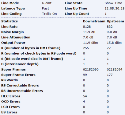 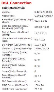 Line Stats from Voyager routerLinestats from Speedtouch router ~ Alphabetical List of line parameters and counters ADR – Aggregate Data Rate. AgR – Aggregate rate.Assumed to be the throughput rate plus overhead bits.B – B ValueNumber of bytes in the MUX Data FrameBER – Bit Error RateThe ratio of Errored bits to Transmitted bits. Line Stats from Voyager routerLinestats from Speedtouch router ~ Alphabetical List of line parameters and counters ADR – Aggregate Data Rate. AgR – Aggregate rate.Assumed to be the throughput rate plus overhead bits.B – B ValueNumber of bytes in the MUX Data FrameBER – Bit Error RateThe ratio of Errored bits to Transmitted bits.BERT = Bit Error Rate Test. Most modem/routers have a tool to check the Bit Error Rate.CRC Errors – Cyclic Redundancy CheckCount of CRC errors. CRC is an error detection code used to verify packet transmission between the sender and receiving end. A CRC error indicates that part of the data packet is corrupt and requires retransmission. – see Cyclic Redundancy Check (CRC) for a more in depth explanation.Many CRC errors in a short period of time will show a noticeable reduction in throughput speed. This can be an early indication that there is too much noise on the line and in extreme situations can lead to loss of sync (disconnection with the exchange). D Value – Depth of Interleaving (INTLVDEPTH)The Depth of Interleaving applied to the line. Various depths of interleaving may be applied by the DSLAM by both BTw and the LLU Operators. See Interleaving for more information. The values range from 1 to 4096. A depth of 1 is the equivalent of Fast Path and no interleaving applied.DelayThe delay due to interleaving being applied on the line – recorded in microseconds.ES – Errored SecondsA one second period of time in which either one or more coding violations occurred OR at least one Loss of Signal events occurred.Its not unusual to see occasional ES and its best looking at the broader picture. Some routers will display the ES over 15 min periods (900 seconds), therefore a couple of errored seconds will probably go un-noticed. BT uses the ES count for its DLM.ESF – Extended Super FramesIn DS1 systems an ESF extends the 12 frames per superframe, to 24 frames contiguously transmitted together. Clarification is needed for the exact amount of frames used in an adsl ESF and reference is given to adsl SuperFrames.FEC Errors – Forward Error CorrectionCount of errors that have been corrected due to error correction being applied to the line. Error correction is turned on at the same time as Interleaving. Its normal to see FEC errors on an Interleaved line and rather than anything to be too concerned about its more an indication that the Interleaving & Error Correction process is working and doing what it should. – See Error Correction for more information.HEC Errors – Header Error Check/CorrectionCount of HEC Errors. HEC is a type of CRC error check which has been performed on the header of an ATM cell, but 1 bit errors can be corrected. This count is usually where HECs have been uncorrected and have been discarded.If these errors are too high within a short period of time it will slow throughput… and could even lead to connection instability – See Out Of Cell Delineation.I – I ValueThe interleaver block size in bytes. Should be a sub-multiple of NINP – Impulse Noise ProtectionLevel of Impulse Noise Protection – See Interleaving ~ INPK Value – Bytes in the DMT FrameNumber of bytes in the Frame. Each Byte is said to give 32 kbps of sync speed. eg (254 available bins x 32kbps = 8128) for downstream and (26 x 32 = 832) for upstream. L – L Value (LSYMB)Reports the actual number of bits per symbol assigned to the latency path in which the bearer channel is transported. This value does not include trellis overhead and ranges from 0 to 65535. (vdsl) or Number of bits in PMD Data Frame (adsl2+) LCD Errors – Lost Cell DelineationCount of the number of Lost Cell Delineation errors – See LOCDLOCD – Loss of Cell Delineation.An alarm state process, different routers may have different alarm periods. A typical alarm integration period may be 2.5 seconds with a 10 second deactivation period.A Loss of Cell Delineation defect is initially triggered when an Out of Cell Delineation (see OOCD) condition occurs and doesn’t clear for more than 4ms. This starts then starts the integration period. If the defect doesn’t clear during the integration period, then an LOCD event is recorded. The LOCD alarm event will clear when an LOCD defect is not detected within the deactivation period.LOF – Loss of FramingAn alarm state process, different routers may have different alarm periods. A typical alarm integration period may be 2.5 seconds with a 10 second deactivation period.A Loss of Frame defect is initially triggered when an Out of Frame (see OOF) condition occurs and doesn’t clear for more than 3ms. This then starts the integration period. If the defect doesn’t clear during the integration period, then a LOF event is recorded. The LOF alarm will clear when an LOF defect is not detected within the deactivation period.LOL – Loss Of LinkPhysical failure of the link. A Loss of Link condition is declared if a Loss of Signal is not preceded by a dying gasp message.LOM – Loss Of MarginNot set on all modems and only relates to adsl2/adsl2+/vdsl. A parameter has to be set for the minimum tolerable noise margin. If the modem falls below this level, then a request is sent to increase the ATU-C transmit power. If an increase is not possible then the line will fail and attempt to re-initialise.LOS – Loss of SignalAn alarm state process, different routers may have different alarm periods. A typical alarm integration period may be 2.5 seconds with a 10 second deactivation period.A LOS defect may initially be triggered when all zeros are received for 20 microseconds which starts the integration period. During the integration period, 2 consecutive frames with 20 microseconds of signal loss will record a LOS event. The LOS alarm will clear when no LOS defects are detected within the deactivation period.A couple or so LOS events may go totally un-noticed during bursty activity such as web-browsing etc. The connection should be able to cope with this momentary loss of signal with the exchange, however a high level indicates a noise problem. Some users have observed that 4 LOF events can trigger a LOS.LPR – Loss of PoweRFailed re-initialisation of the DSL link due to power loss. A dying gasp message has been sucessfully sent/received.M – M ValueMUX Data Frames in FEC Data Frame or Number of Mux Data Frames in a RS codeword.MSGCNumber of bytes in the overhead channel message.N – N Value (NFEC)RS codeword size. Reports the actual number of Reed-Solomon redundancy per codeword used in the latency path. Used with the R value to express the rate of FEC applied.NCD – No Cell DelineationSee LOCD – Loss of Cell DelineationOCD Errors – Out-of Cell DelineationCount of out-of-cell delineation errors – see OOCD.OHF Errors (OHFErr)Overhead Frame Errors. Similar to CRC Errors.OOCD – Out Of Cell DelineationOut of Cell Delineation event occurs when seven consecutive cells fail to contain a valid HEC (Header Error Check). An OOCD clears when six consecutive HEC valid cells are detected.OOF – Out Of FrameAn Out of Frame event occurs when four consecutive frames do not contain a valid frame word. OOF clears when two valid consecutive frames are detected.OR – Overhead RateR Value – RS check Bytes (RFEC)Number of (redundant/parity) bytes occupied by the Error Correction process (overhead). Often used to describe the level of error correction and can range from 0 to 20. The more check bytes that are used then the more errors can be corrected. The value 0 indicates no Reed Solomon coding. Use this value with N to express the rate of FEC applied as a percentage. eg R/NRS Correctable ErrorsThe number of Reed-Solomon code words with correctable errors. Reed-Soloman is a method of Forward Error Correction and therefore a count of data successfully recovered. See FEC.RS Uncorrectable ErrorsThe number of Reed-Solomon code words that had uncorrectable errors. Reed-Soloman is a method of Forward Error Correction. Uncorrectable Errors are those that are too severe to be corrected by FEC.RS WordsCount of the total number of Reed-Solomon code words transmitted/received.S – S ValueRatio of FEC over PMD Data Freme length or Number of data symbols the RS codeword spansSES – Severely Errored SecondsAs the name indicates this is more worse than an Errored Second (which only needs one event to trigger an ES). A Severely Errored Second is a one second period which contains 30% or more errored blocks OR several other events such as one or more OOF.Note: It has been observed that a LOS event may be preceeded by a SES if the LOS was not preceeded by a LPR event. ie The dying gasp message appears to prevent an additonal SES being recorded before an LOS.SF – Super FramesTraditionally, a (Digital Signal 1) superfame consists of 24 frames contiguously transmitted together.In adsl, a superframe consists of 68 adsl frames plus a synchronisation frame. The adsl modem generates 4000 frames per second. The global duration of an adsl superframe is 17ms.SFE – Super Frame Errors (SFErr)Count of the Super Frames received which had an error. This is similar to CRC error.T – T ValueMUX Data Frames over sync bytes or Number of Mux Data Frames in an OH sub-frameTotal ES / ESFThe total Extended Super Frame errors – See ESFUAS – Unavailable secondsTen consecutive SES’s will trigger a UAS event, and will remove the path from use. The path will become usable again after 10 consecutive seconds with no SES.A count of UAS events can be triggered by a LOS event and will continue to accrue for each second that the system is up and the path is unavailable. ~ Reed Solomon Parameters (Error Correction)MSGc = Number of bytes in overhead channel message K = Number of bytes in the DMT Frame B = Number of bytes in the data frame N = NFEC = Length of codeword (N = K + R) R = RFEC = RS check bytes / Amount of redundancy S = Symbols per codeword / No of data frames per codeword T = Number of dataframes in an OH subframe/ Data frames over sync bytes Q = Number of RS codewords per DTU (g.inp) V = Number of padding octets per DTU (g.inp) ~ Interleaving ParametersI = Number of Interleaver branches / The interleaver block size in bytes. Should be a sub-multiple of N. J = Interleaving depth. (J = M * K + 1) K = Interleaver block length. K = L symbols (equal to or divisor of N) M = Incremental delay / Number of Mux Data Frames in FEC Data Frame/RScodeword D = Interleave Depth. (D = M * I + 1) L = LSYMB = Number of bits per symbol in the latency path / Number of bits in PMD data frameInterleaving introduces a delay of M * I * (I-1) Actual delay – ADSL shown in ms = [S x D]/4 Actual delay – If retransmission is used this specifies the actual value of the time independent component of the delay due to retransmission only.Note: VDSL uses a triangular interleaver.~ G.INP Retransmission Parameters & Countersrtx_tx = Count of retransmitted DTUs. rtx_c = Count of detected and corrected retransmissions. rtx_uc = Count of detected DTU errors which have not been corrected within the delay_max constaint.EFTR = Error-free throughput SEFTR = Severe Loss of error-free throughput LEFTR = Loss of Error Free Throughput – Count of seconds with a defect errFreeBits = Error-free bits counter – bits originating from the DTU that have been detected to contain no error at the moment of crossing the β1-reference point.minEFTR = Minimum Error Free Throughput minEFTR is a performance monitor measured at showtime of the minimum of the EFTR observed in the seconds since the last reading of the EFTR_min, excluding the following seconds. – seconds in which the values of EFTR are less than ETR/2; – seconds in which EFTR is not defined; – the single second preceding a second with seftr defect; – the single second following a second with seftr defect. |
[note: appears to bear some resemblance to sync speed]
The interleaving used on Latency path #1 shall be a block interleaving. The interleaving block shall have a size of D1 × NFEC bytes, with NFEC being the length of the RS codeword, and D1 being the interleaving depth. If D1=1, then an interleaving block equals an RS codeword. If D1=Q (the number of RS codewords per DTU) then an interleaving block equals a DTU. Each byte Bk within an interleaving block (input at position k, with index k in the interval 0 to D1 × NFEC – 1) shall be located at the output of the interleaving function at position l given by l = i × D1 + j, where i = k MOD NFEC and j = floor(k / NFEC).